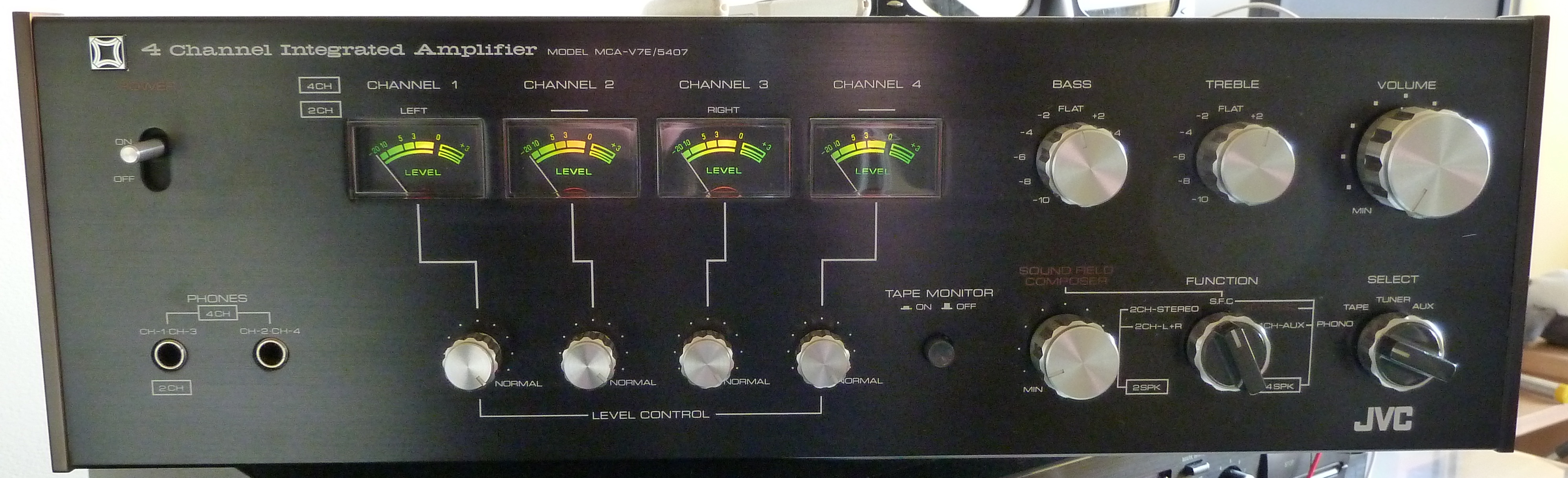
For some reason I wanted to do a recap job of my vintage quadraphonic amplifier, the JVC MCA-V7E that you see above. This unit is actually in very good shape, so the reason for me to do this is also unclear to me, really! But sometimes my ways are inscrutable.
recap
A recap job means that you replace all the old, worn out electrolytic capacitors that are >40years old with new ones, preferably audio-grade types. Electrolytic capacitors are known to dry out when they get older. And then they lose their characteristics. Worst case is that they short out, or that they start acting as a coil or as a resistor. These are all things that you do not want in your amplifier. Or in any other device, for that matter. Also, the original caps were never the same quality as the ones that you can buy today just because manufacturing, tolerance and materials have become so much better in 40 years. So in theory this should enhance the performance of the unit.
Also, it is not a question if an electolytic caps will fail, but when. So after the recap your equipment will be good for at least another 40 years, but probably a whole lot longer.
Panasonic FC series
If you are gonna do it, you want to do it good. Then you go for the audio-grade caps.
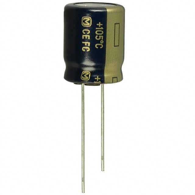
These black caps are available at sometimes crazy prices of several euros a piece, but there is a very good capacitor at a very reasonable price. So all audio enthousiasts like me that do not have a money tree in the backyard use these FC series caps, as you will probably need a good bunch of them. In this case I used around 50-60 of them, but I have not counted them exactly. I ordered them from farnell.nl they have the complete range of values at good prices. The only problem is the minimum order amount of 50 euros.
The works
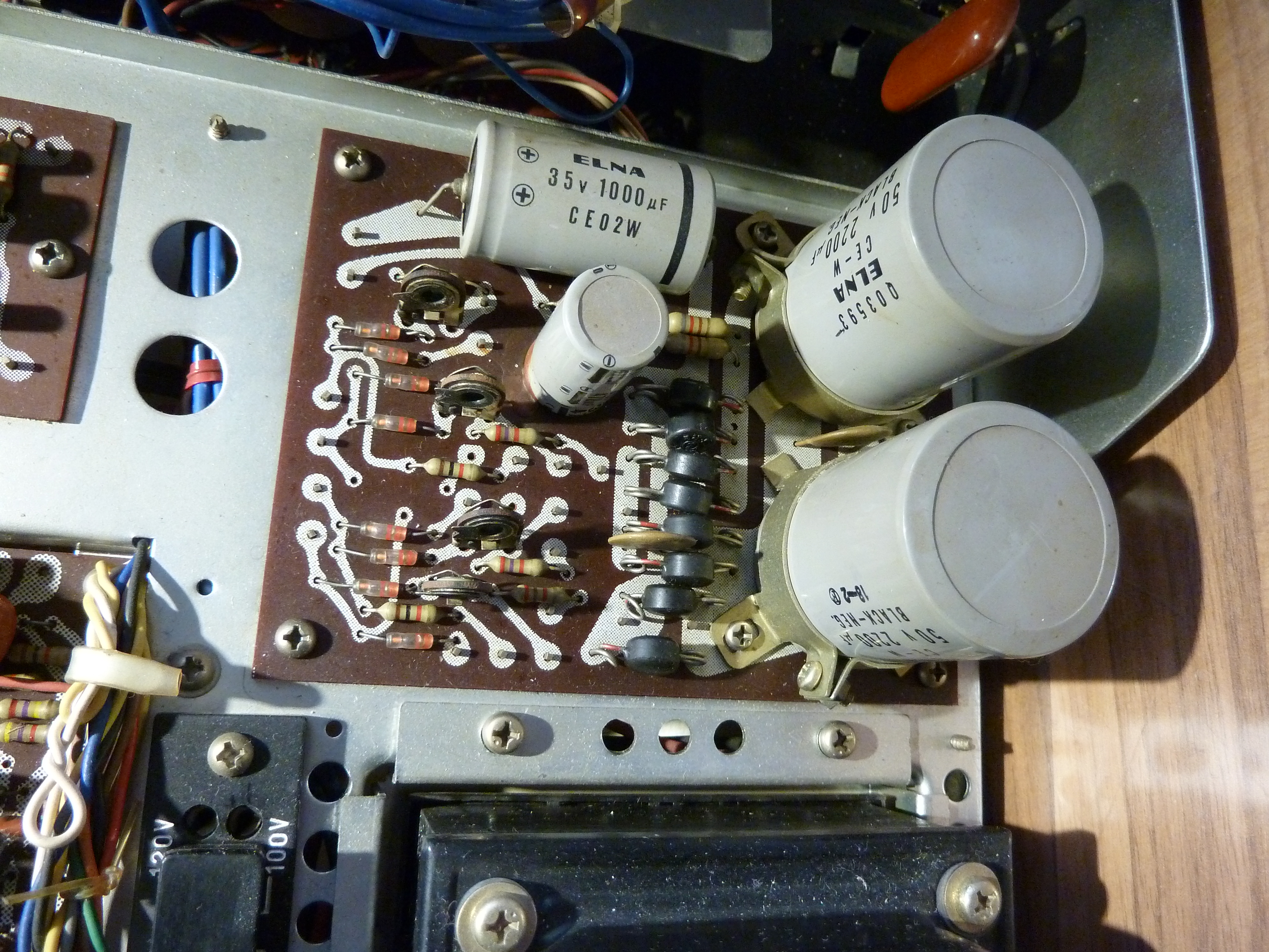
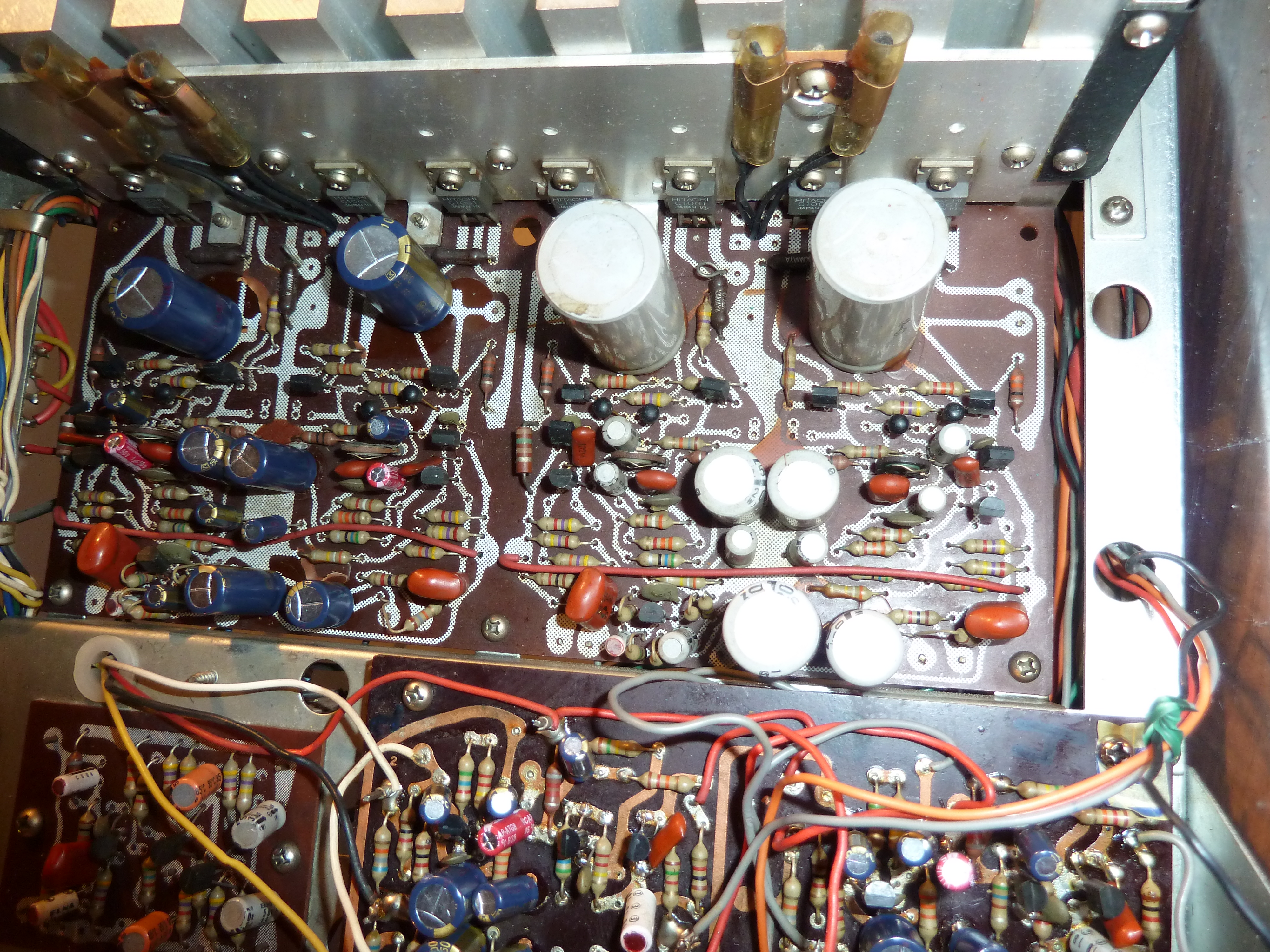
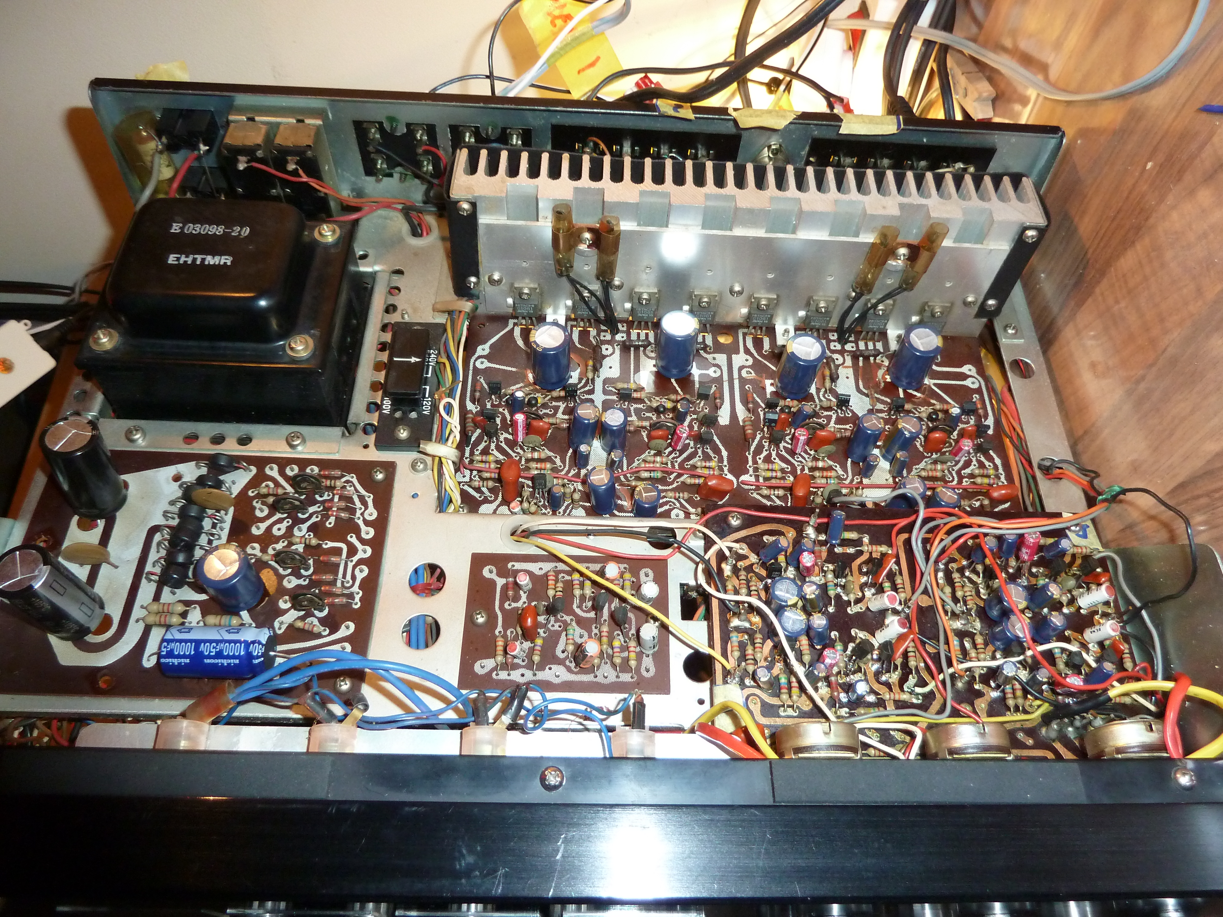
This is what the unit looked like before I started:
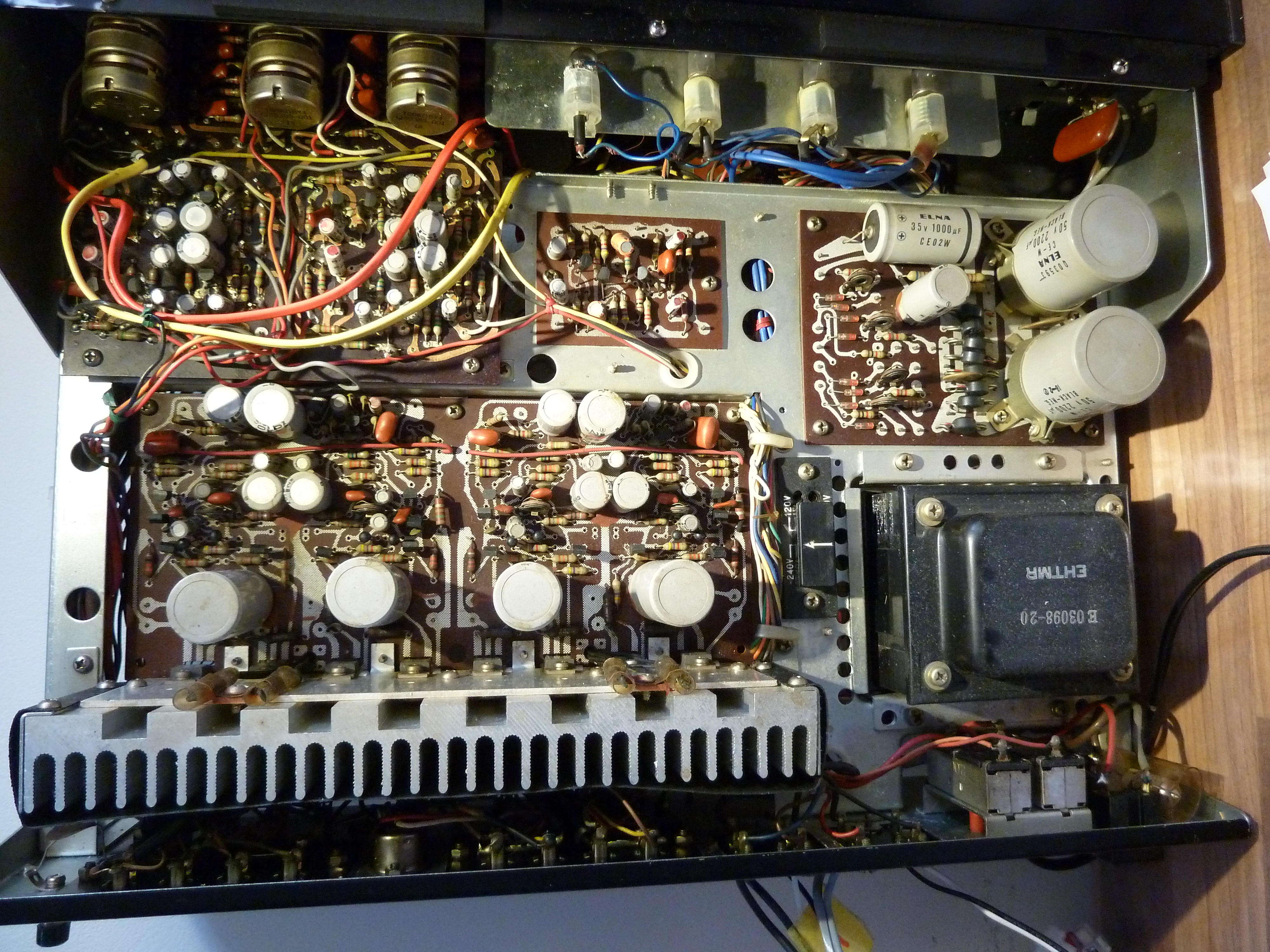
Basically all the grey capacitors that you see here had to be replaced. This consists of the Power Supply board, the tone/preamp board, the mainamp board, and the phono board which is located on the underside
I started with the PSU (power supply). These contained some big ones.
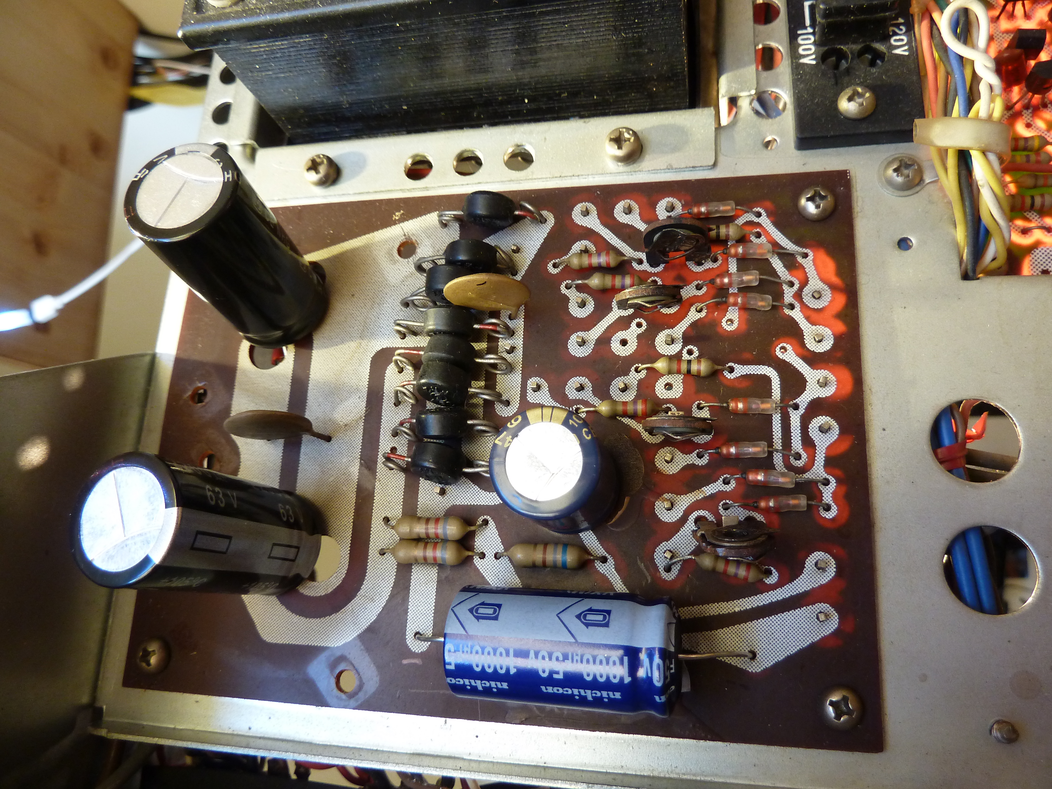
PSU after
PSU before
Note the difference in size. The new ones are a lot smaller. They have the same value nevertheless. After I had done the power supply, and the amplifier still worked (!!) 🙂 I tackled the phono board.
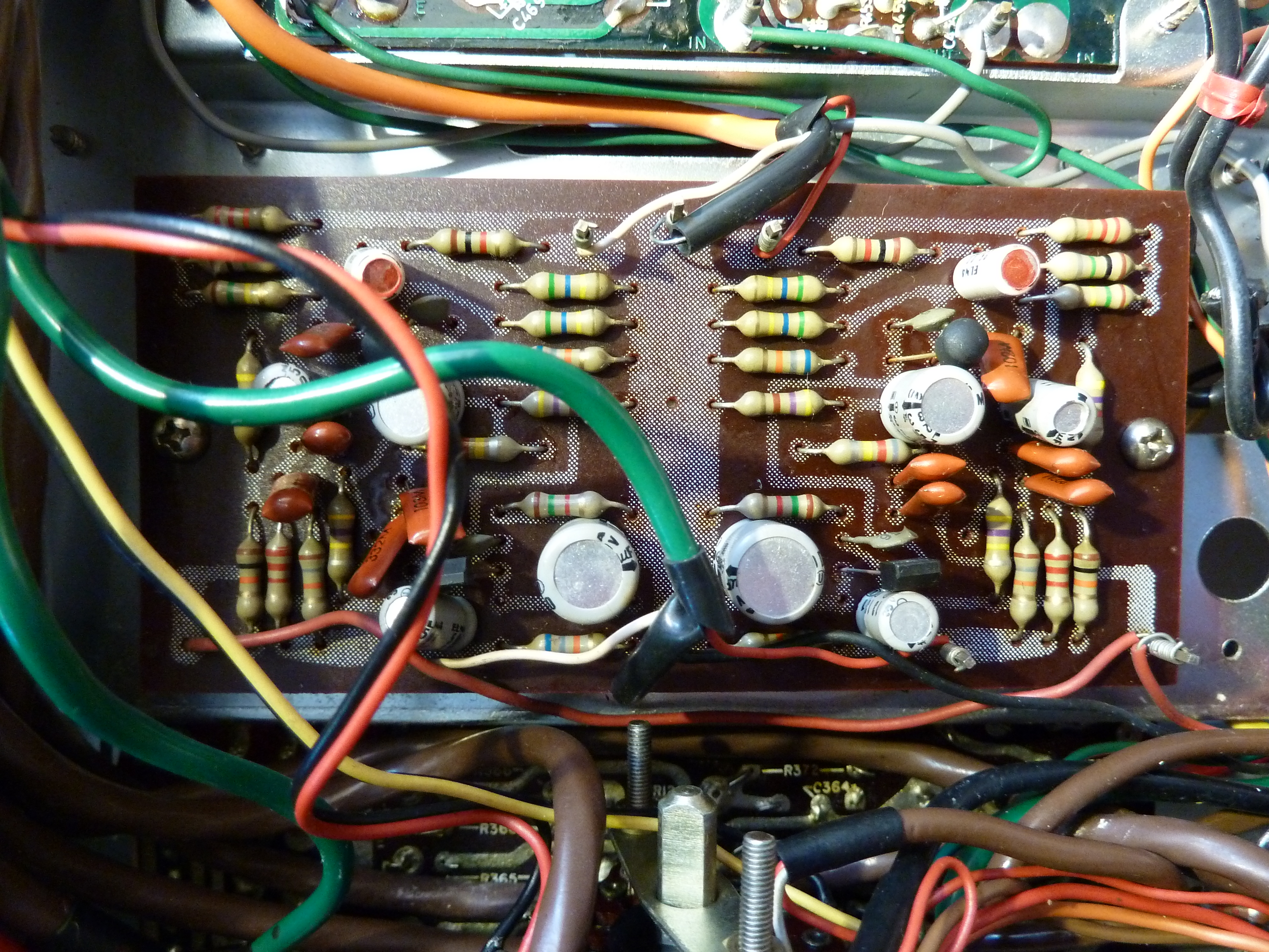
phono before
And then the preamp.
premp done
preamp before
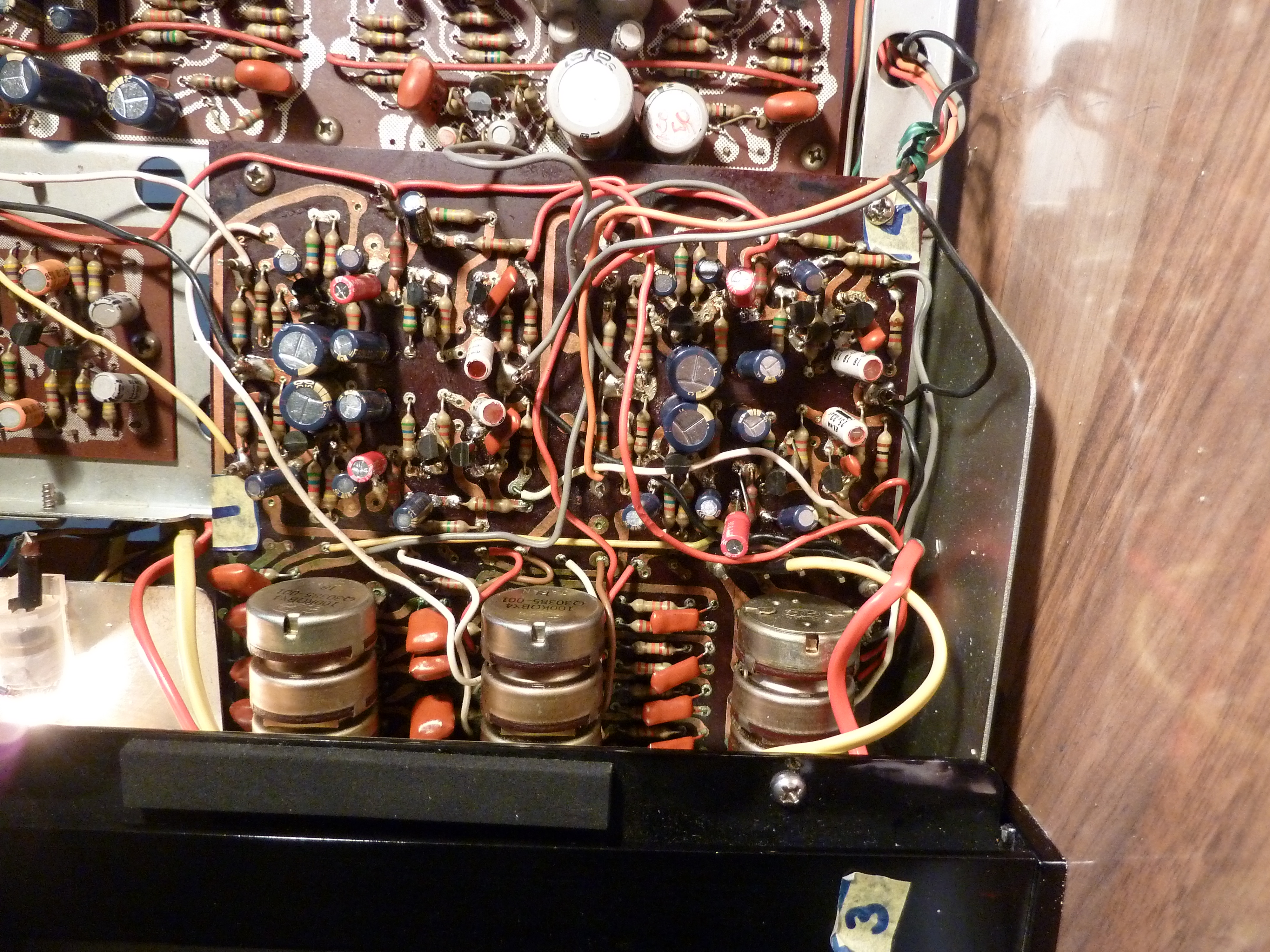
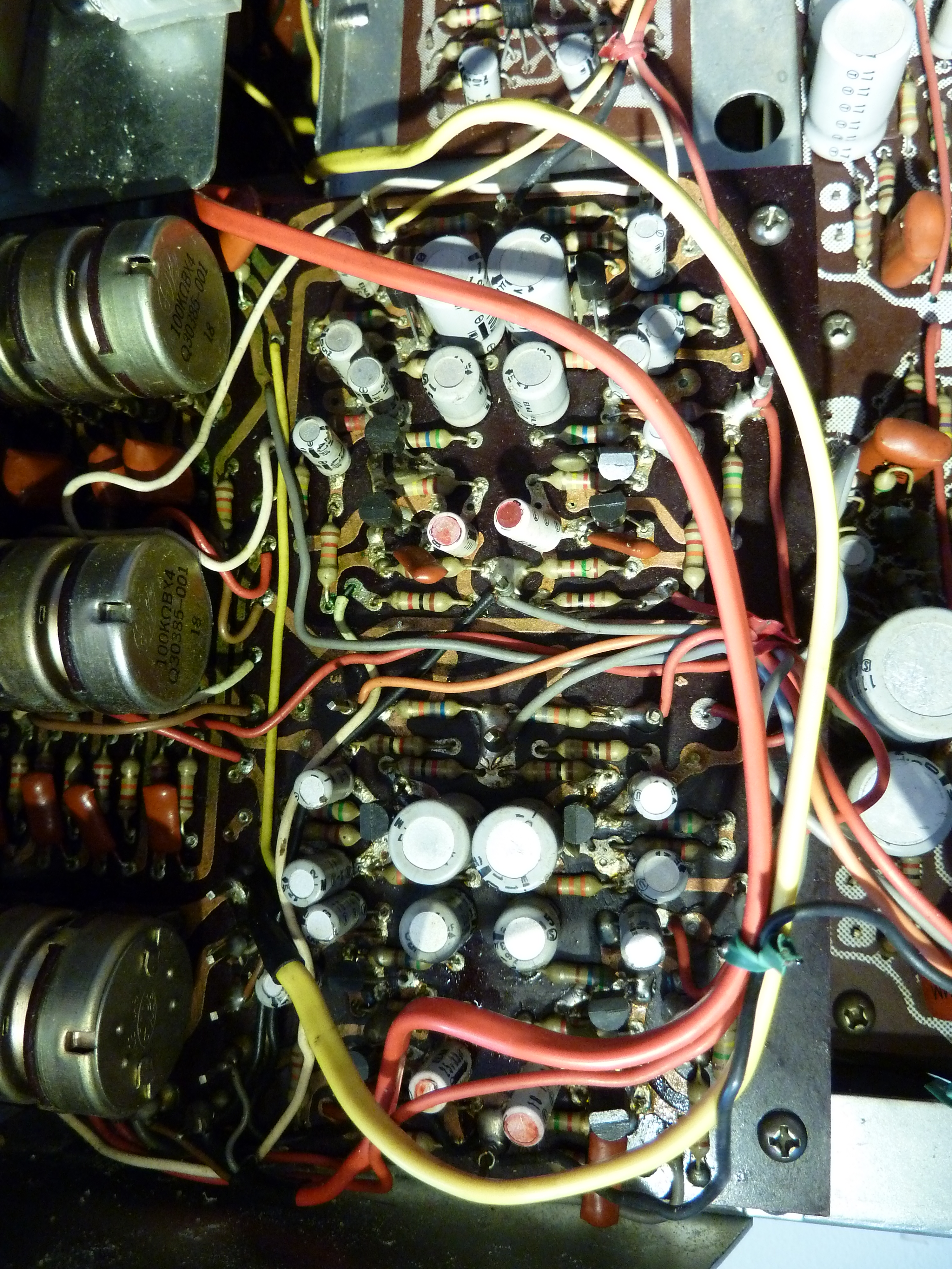
And then the main amp:
halfway
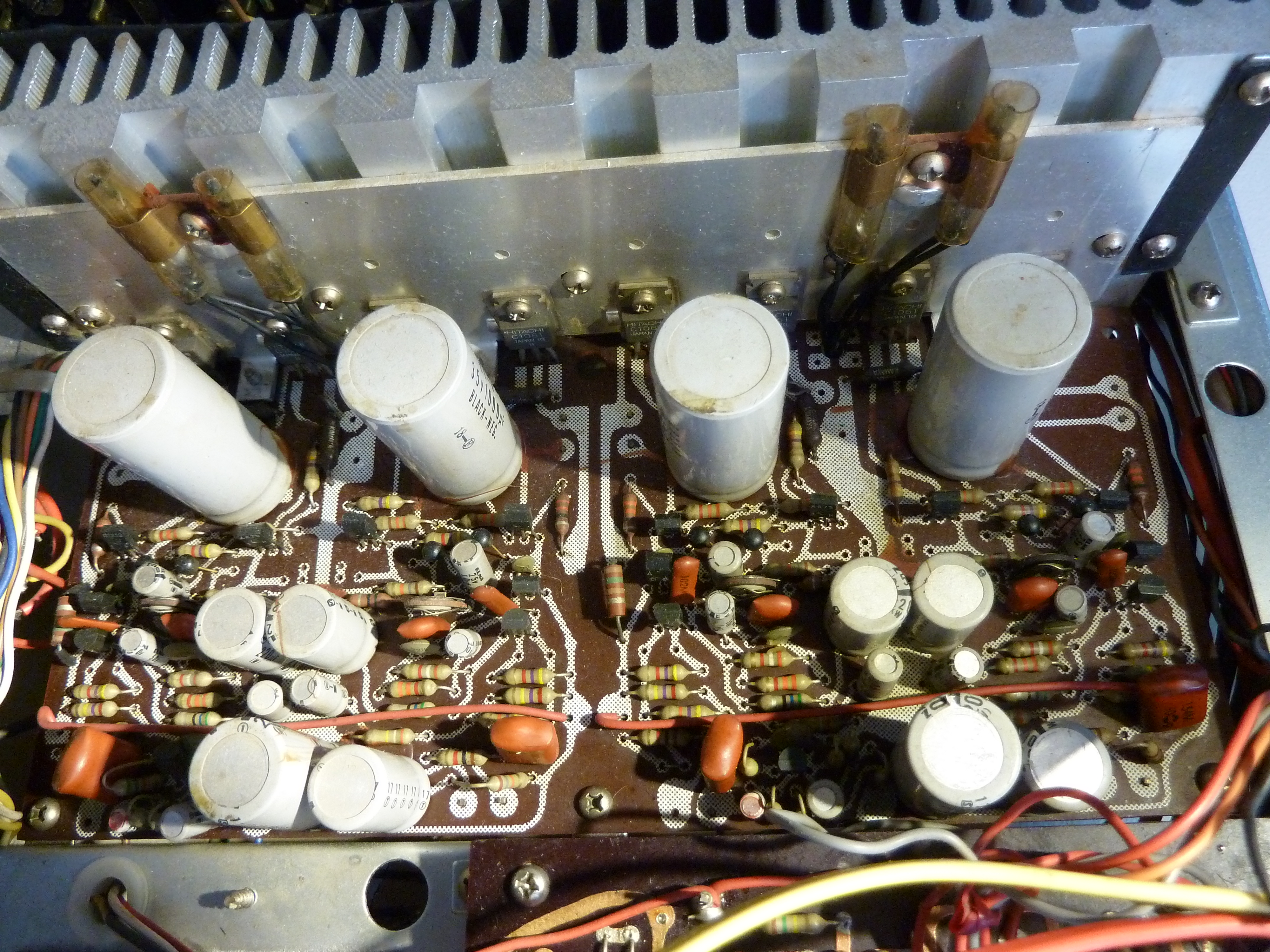
before
all done
After all the works was done, it was time to turn the power on. Exiting! Nothing exploded and no component was getting very hot, so I connected an input signal on the four inputs and turned up the volume. Channel 3 was not working. Hmmm. I remembered a problem I had when removing the large capacitor from the third channel, when the copper strip had come loose from the board. On closer examination I saw that it indeed was not making contact properly anymore, so that was easily fixed. Now the 3rd channel worked ok!
The sound from the ‘new’ amplifier is very crisp, someone called it ‘clean’. I think that is an apt description. I turned the JVC up quite a bit, and experienced no problems. So I am very happy with that.
Testing & measuring
Next up is a bit of testing and especially measuring. Because I wanted to test some new type of transistors, I have installed them in the channel 2 pre-amp. I want to see how they stack up against the original ones. I am especially interested in distortion and overall performance. If they don’t perform well, I will re-install the old ones. Maybe the amp needs to be biased as well, but I’m not sure yet.
I also turned up the calibration on the meters quite a bit, so now the needles are showing signal even at normal volume levels, that was not so before. Previously they just lingered around in the left corner doing mostly nothing.
I have provided here a simple drawing of the electrolytics on both amplifier boards for your convenience, if you should decide to do the recapping as well. Good luck!
Hi –
I’m sorry I don’t know your name, but my name is Ken. I am fortunate enough to own one of these, and it serviced me very well in the 70s. I had many requests from my parents to turn it down back in those days. Anyway, I have had it in storage for many years and decided to drag it out to see if it still worked in hopes of selling it to gain space or even possibly using it. it appears to be in great shape. After cleaning it up a bit I tried it out with a cassette deck. I used the 2 speaker setup and the right channel sounded fine. The vu meter (no. 3) worked about how I expected at various volumes and the sound was fine. The left channel produced a low volume noise with a lot of static. The left channel vu also moved very little. I disconnected the left speaker and the vu appeared to be working properly at various volumes. I decided to try headphones and they worked perfectly in both stereo and mono settings. I continued fooling with it and never got any improvement in the left channel while connected to a speaker. Eventually the protect switch clicked and I lost power to that channel. I reset it and have been trying to get it to do something, but it continues to trip no matter how low the volume is set both on the master volume and the volume setting for channel no. 1. I have also looked around and have not been able to find an obvious short circuit.
I would really like to get this thing up and running again. I am not an electronics expert, so replacing caps and such is out of the question. Any suggestions you might be able to offer to a layman not familiar with such things would be greatly appreciated.
Hi Ken,
Have you tried switching the speakers?
-Philip.
Nice work Phil, your dedication to this amp inspired me to fix mine, as i picked it up at a yard sale for $10 ,of course when i bought it i knew it was going to need some kind of work,so instead of throwing it in the bin after finding out that indeed it was un listenable due to the garbled sound coming out of it i did the homework & found your work,cheers bro & hey what a bitch was that tone board was to work on,what were they thinking when the designed that,clever those Japanese,tee hee
Hi Phillip –
Thanks for your quick reply.
Yes, I’ve tried switching the speakers, reversing the RCA left and right inputs and the left channel still trips the overload protection even with no speaker attached and the volume for the left channel reduced to 0. It seems like an internal problem within the amplifier. When I press the red button all of the vu meter lights dim and it trips immediately. Is seems as if the whole amplifier is affected, but the right channel still keeps working. As I’m sure you’re aware, one reset button is for channels 1 & 2 and the other is for channels 3 & 4. No problem with 3 & 4. Channel 3 (right) is playing fine.
Thanks,
Ken
Ken,
That is a difficult problem to troubleshoot. I suggest you contact a knowledgeable local repairshop and let them have a look at the problem. Could be simple, could be complex.
Sorry that I can not help you further.
Phillip –
Thanks a lot for your input. It has been great chatting with you.
Best regards,
Ken
Hello, Ken a long time has gone by on this post but incase you sill out there,i just rebuilt this amplifier as it was in pretty bad shape but it had the same problem you speak of,the left channel is channel 1 on the unit, the circuit board is divided in to 4 sections, 1&3 are the left & right channels.i replaced a 2sa1268 transistor on section 1 & straight away the distorted sound was gone, you can order these transistors through ebay for chump change.pretty easy to install,it’s like following a cooking recipe,cheers, oh yes i changed all caps & other transistors,especially the main output transistors 2sc1061,ebay again, this thing is nearly 50 years old so it needs a helping hand
Hi Philip, do you know how the wire is called at retailers that is used inside the old amplifiers?
I have an old amp that needs service and noticed that the wire used, is short in length and tends to break easily.
I order at Reichelt but I cannot find the right product as yet. Only thing found so far is installing grade for house use. So that is the stiff kind you find at the hardware or DIY store.
Not sure which gauge and grade. In some cheaper products the wires that were used aren’t even made of copper.
Danny
Hi Danny, not sure what you mean exactly. Do you mean the small wires to interconnect the PCB’s?