I’ve been working on a way to control my HP8903A Audio Analyzer directly from my PC. This precision instrument is a fantastic tool for audio measurements — think frequency response plots, THD+N distortion analysis, and more — making it ideal for testing tape machines and other vintage audio equipment.
I also have the necessary GPIB-to-USB interface from National Instruments (NI-488.2), which handles the communication between the analyzer and the computer.
There is already excellent software available for this purpose, written by Peter Millett. You can find it on his website at http://www.pmillett.com/hp_8903_software.htm. Peter was kind enough to share his source code with me, which turned out to be invaluable during development.
However, his software had a few limitations that didn’t work for my setup:
It is a Windows-only application that requires a specific HP runtime environment.
It was written in an HP proprietary programming environment that is difficult or impossible to install on modern versions of Windows — and since it is commercial software, extending or updating it would require a financial investment.
I work exclusively on Linux and don’t have a Windows machine available.
I wanted a fully open-source solution that others could possibly freely build upon.
So, with some help from AI, I set out to rewrite the application in Python. The result closely replicates all the functionality of Peter Millett’s original software, while adding cross-platform support and a modern interface built with Qt6 and pyqtgraph, running on openSUSE Tumbleweed with Plasma 6.
The application is still technically a work in progress, but it is 95–99% complete and currently running flawlessly. Only a few small refinements remain.
Here’s a screenshot of the current interface:
The app supports four core measurement modes:
Frequency Response — sweep the input frequency and plot the output level across the audio band
THD+N distortion — measure total harmonic distortion plus noise at a given frequency and level
Voltage — read AC/DC voltage at the analyzer’s input
Power — measure output power into a specified load
Very happy with the result, and it works very nice!
DISCLAIMER: This program is tailored for my situation. Even though it is made using 100% open source components I am not sure that it is very portable and that it works in your situation. Leave a reply (link is above post) if you are interested, but I do not have high hopes that it will run outside of my environment. But you can always have a go. Please let me know if it has worked for you (especially Windows users), or if it didn’t work for you. Hopefully I can improve the code, or the setup process so that we can make it work everywhere.
I have created a Codeberg repository that you can clone here: https://codeberg.org/pvdm/hp8903a There are instructions on how to install the app on your system.
Next project: do the same for my Audio Precision Portable One Plus:
10 thoughts on “HP8903A Audio Analyzer and python: creating a new app”
Curtis H
Hi, I would love to try out your 8903B py software. Your help file specifies very carefully py version and lib versions. I have a lot of SW experience, so I feel that I can beat it into submission.
I have built pete millet jonokuchi headphone amp, a 2nd with boutique transformers, sangaku headphone nutube amp, his mighty midget, 26a7 preamp. Working on his engineers EL84 amp.
Also built a tubelab TSE with 2a3 tubes.
I have an 8903B and usb interface and would love to get measurements going on all these amps.
I have created a codeberg GIT repository. I have uploaded all the files there. It works very well, but since I run a rolling distribution (openSUSE tumbleweed) The GPIB driver breaks a lot. Every time I get a new kernel, about once a week. But there is now built-in DKMS support so that the GPIB will be rebuild after each update. But check in often, it is still being ‘perfected’ so whenever there is an update, I push the new files. Also after you have ‘git cloned’ the repository, be sure to check out the README and the help files.
You can find the git repository here:
I am very interested in getting this going as well, however I am using a standard PCI type interface, which is working on Pete Millets software in windows, but I cannot seem to get your version working unfortunately. I have tried it in linux as well, but as you mentioned there are so many variables. I would like to get it working on linux preferably, windows would be acceptable because I have other test equipment hooked to the same GPIB interface on it anyway.
A brilliant open-source solution! Moving away from legacy Windows dependencies to a clean Python-based architecture is a pro-move. As an Electrical Engineering student at Telkom University Surabaya, I really appreciate your effort in making this instrumentation data accessible and extensible.
First of all, a very nice and neat GUI.
I tried the script under Windows 10 with a PCI NI488-2 card, but it did not work well.
So I rewrote the script a bit, the interface for Windows and I must say it works perfectly.
But one question, have you already implemented the filters?
I work with the HP8903B and I do not have HP filters but a CCITT filter, so it is very possible that there is another command for this.
I would only expect the HP filters to work if you have activated them in the script, otherwise I will continue looking.
Thank you so much!
I think it’s amazing you got it working under windows.
I have not updated the app, if I would have it would have been pushed to codeberg.
My question is whether I am doing something wrong with the controls or if the filters in the script are not yet activated?
The keys work, but nothing happens on my instrument yet; I currently have the B version and a CCITT filter instead of the HP filters.
If the filters are not yet activated, I will see if I can add this to the script.
If you would post my changes—the complete script for Windows 10—along with your script for Linux, I will send it to you so that everything remains organized together.
Are you talking about the high pass 400 Hz and the low pass 30/80 kHz filters?
I do believe this functionality works on my machine with the app. It has been a while. I can not verify it atm.
And yes, I would like to eventually include your script in the codeberg repo when it is working, with the proper credits of course!
I recently purchased a TASCAM BR-20T. It was on my wanted list for a long time, because it looks beautiful and the operation is super smooth. And now I came across one that was very nice and looked like new. So I got it and took it home. It is a 2-track deck with time code, although I will not be using that of course.
Of course there were some minor issues with it: like the belt needed changing, and there were problems with the pinch roller and the reel tables, but nothing that could not be resolved quickly. So here is a picture of my new beauty.
Meanwhile, I opened up the deck and replaced the belt, did some Service Manual adjustments, did some tension settings, and calibrated it to PER528.
Now it sounds very good. Before I put it back together again, I took the EPROM and dumped the content to a file. It is on my site, in the STUDER page in the ‘EPROM and firmware’ section, should anyone need it.
I was searching for a list of Reel To Reel decks that are able to play 2 track fulltrack professional tapes, as well as 4 track consumer tapes.
Head layout
This is a diagram showing possible head configuration for 1/4 inch tape. So in the example above that would be option F and G: F is the 2 track full track, and G is the 4 track layout of which 2 tracks are played. Also, FYI:
option H is used in 4 track reel to reel machines like the Teac A-3440 et al.
and option I is used in 8-track 1/4 inch multitrack machines like the Fostex R8 et al.
The list
After some digging around I came up with this list of reel to reel decks that can play both 2 track and 4 track tapes which I believe is fairly complete:
Akai 400d PRO
Akai PRO 1000
Denon DH-710F
Otari MX-5050BII
Sony TC-766-2 (Japan: TC-R7-2)
Sony TC-880-2 (Japan: TC-8750-2)
Teac A-6100
Teac A-6700DX
Teac A-7400(rx)
Teac X-1000M
Teac X-2000M / TASCAM 3030
Technics RS1500 (Rec 2T PB 2T and 4T), RS1506 (Rec 4T PB 2T and 4T)
And now?
For find a deck with pleasing aesthetics for in the living room, my pick would be the Tascam 3030, but the 2 Sony’s and the 2 Technics are close 2nd and 3rd. And since we found the Teac A-6700,
well that’s a very interesting option too!!
If you happen to know or find other models that can play 2 and 4 track tapes that are not listed here, please do not hesitate to leave a comment so I can make this list as complete as possible!
HP notebook does not work, there are several fixes and tweaks to the system that can be tried. I have literally tried all of them, and believe me, they all DO NOT WORK.
What is the problem? The suspend function in linux works ok, because
# systemctl suspend
works flawlessly. But it does not work when setting the events in KDE plasma Power Management settings. Believe me, it simply does not work.
Then I tried a LOT of other options, ranging from GRUB kernel boot options to creating custom ACPI events and letting systemd logind handle the event etc. etc. etc.
I spend a lot of time, none of the options worked for me. Finally this solution worked. it uses a service to manually suspend the machine (since the command does work normally).
#!/bin/bash
exec > /var/log/lid-suspend.log 2>&1
echo "$(date): Lid poller v2 started - checking all paths"

while true; do
  for path in /proc/acpi/button/lid/LID*/state /proc/acpi/button/lid/state /sys/class/input/*/uevent; do
    if [ -f "$path" ]; then
      if grep -qi "closed\|LID=closed" "$path" 2>/dev/null; then
        echo "$(date): Lid closed op $path - suspending!"
        systemctl suspend
        sleep 15
        break 2
      fi
    fi
  done

  # Fallback: input event checken
  if ls /sys/class/input/input*/name 2>/dev/null | grep -qi lid; then
    echo "$(date): Lid input device gevonden via fallback"
  fi

  sleep 1
done
and have always wondered why PulseAudio had a fixed setting for sample rate,
but thought that that situation would improve when PipeWire got established,
and then learning that PipeWire STILL had a fixed sample rate?
So that everything was resampled to 48000, or whatever setting was the default?!
Fear no more.
THIS is how to make PipeWire always choose the best sample rate when playing audio. So that a 44100 Hz files will play with a 44100 sample rate, and a HiRes 96000 file will put the soundcard at 96000.
open, or create, ~/.config/pipewire/pipewire.conf and put this in: context.properties = { default.clock.allowed-rates = [ 44100 48000 88200 96000 ] } if required, add extra sample rates that your files and/or your soundcard supports.
That’s it! Maybe need to log out/in, or kill PipeWire, whichever you choose
check the result with # pw-mon R 52 4096 96000 83,3us 16,5us 0,00 0,00 0 S32LE 2 96000 alsa_output.usb-Focusrite_Scarlett_2i2_USB-00.HiFi__hw_USB__sink R 72 7200 96000 41,0us 22,4us 0,00 0,00 0 F32LE 2 96000 + LibreWolf
Both the hardware (Focusrite) and the program (LibreWolf) are playing audio at 96000.
I found that in order for Qobuz (and probably other streaming services as well) to really play at native bit rate, LibreWolf will do the trick, NOT the ‘native’ linux flatpak client for Qobuz. So use the url: ‘https://play.qobuz.com/’
Today I am fixing another Fostex R8 from a customer. The problem was that the plastic capstan wheel was slipping on its axis, and the spooling motor wheels did the same. This is a common problem with these decks. The Fostex will not play and/or spool correctly then.
Fortunately, John from https://www.tascamninja.com/ makes aluminium replacements. These fit tightly on the axis and can be fastened with a screw.
I also replaced the belt. Now, the deck plays and spools perfectly.
A small problem
But unfortunately, one problem remains: the arm on which the right tension roller is mounted, has got a fair amount of play, maybe caused by a blow or something. This is causing the right tension roller to guide the tape in a skewed position. It is not a show stopper, but it is certainly not ideal for the tape path.
Beste Philip, ik heb een Fostex R8 en de rechter motor aandrijfsnaar is niet goed. De recorder gaat verkocht worden, maar moet helemaal goed gecontroleerd en waar nodig gerepareerd. Kan dat op korte termijn en wat zijn de kosten? Ik hoor het graag! Alvast bedankt en tot ziens, met vr. grt. Mac Sell-macsell@ziggo.nl-T 0611239374
De getande snaren van de spoelmotoren en de rubber capstan snaar zijn vrijwel altijd vergaan in deze modellen.
Dit zou ik voor je kunnen vervangen, zie mijn site voor de reparatietarieven.
Echter, ik keek net bij de leverancier waar de nieuwe verkocht worden en ze zijn uitverkocht. Ik weet niet of er nieuwe komen. Ook heeft deze site een levertijd van enkele weken weet ik uit ervaring.
Wat betreft een spoedreparatie: dat is te regelen, op voorwaarde dat ik de benodigde riemen snel kan vinden en geleverd kan krijgen. Hierdoor zullen andere klussen echter moeten wachten en er zijn extra kosten aan verbonden.
Oh, en je email adres klopt niet, want mijn email bouncde. Kun je dit aanpassen?
-edit- oh ik zie het al, WordPress plakt er iets aan vast wat niet moet.
Recently I got in contact with the owner of a Mastering Studio. He owns a Studer B67 and had a problem with it regarding calibration levels. He wants to use the B67 as a ‘bounce to tape’ device to get the tape compression-effect. And there was also the problem of randomly dropping levels when calibrating.
When I got the deck I could replicate the problem with the levels. I It seemed weird to me, but I suspected that the REC AMP cards, or maybe the Power Supply was faulty.
The deck had been fully recapped and serviced before. And I can say that the person who did that did an outstanding job! No complaints whatsoever.
I spend a lot of time diagnosing the problem, measuring every aspect of the deck, checking pots, solder joints, etc. etc. whatever I could think of. I found one shorted tantalum cap in one of the REC AMP cards, but I wasn’t sure if that was causing the problem. The card was functioning normally. I replaced the tantalums for quality elec. caps.
After a lot of testing, the problem seemed to have gone away, as I could not replicate it anymore. It could very well be that the initial tape used to test the deck with, was not performing as it should. Anyway I tested the deck with my own BASF 911 tape and I found no problem anymore.
So I continued with the second item on the list: recording the middle speed of 19 cm/s with such a high fluxivity that tape compression could be achieved easily without over-driving the input chain too much. At the end I put the slow speed ~@320nWb/m, the middle speed ~@510 nWb/m, and the fast speed also at ~@320nWb/m, as per the customer’s wishes.
Of course. So I just got my Studer B67, from Germany, and I was still very much enjoying it, when the opportunity arose to buy a Studer A810. I know. When it rains, it pours.
The Studer A810 came from a company that services professional studios all over the world, and has been in their possession for a number of years and was still in use regularly. So it came with a bit of assurance that it would be OK. It had been recapped and kept in good working order.
The price however, was very steep. So that price, and the fact that I had júst gotten my B67, made me hesitate to buy it. I doubted a lot, and then some more, but I finally took the plunge and did it anyway. I did it also because in 2014 I bought my Studer A80 also at a (then) high price, but that price is now a joke. It’s nothing. It is worth so much more now. And I never ever regretted the purchase.
So then it was a matter of getting the deck. It is a bridged version, which means that the deck is in a console with an overhead VU-meter bridge attached. It is a complete package, but it is also a challenge to transport. Luckily the company that I bought it from, offered to bring the package to my home in their truck. They often have to do this I suppose in their line of work, which is servicing studio equipment.
Package for you!
So a few days before Christmas 2021 a big yellow truck pulled up on my driveway and 2 guys stepped out. I was very excited as they wheeled the A810 into my garage.
We had a nice talk about it and taperecorders in general. After they had gone I wheeled the deck into the living room, because, as it was a cold damp day, the deck needed to be acclimatized before turning it on.
The first power-up
So the next day, after having spent the night in our living room, and being all warm and cozy now, I dared to turn the A810 on for the first time. You only get this feeling once! After loading a tape I plugged in a pair of headphones, as I have no equipment to hook it up to in the living room. I have a nice tape that is recorded on my Studer B67 that sounds great. The deck and the tape did not disappoint!
I played around with it and I was pleasantly surprised at the smoothness of the tape handling. I got myself familiar with the keys on the keypad and their functions. I loaded some pancakes to try out, and that too was very enjoyable.
I was a bit disappointed because there are 2 headphone connections, one in the bridge and one in the deck. The one in the bridge turned out to be mono, and the volume of the connection in the deck was way too low to be able to listen to the music at a normal level. I could of course do that upstairs, but that would have to wait a bit until we managed to get the console upstairs.
Then, I was very curious to find out about the various cards in the machine. I opened the flap, or tray or however you want to call it, at the bottom of the frontpanel with a hex key and found this:
From left to right: MPU Unit 1.820.780.82 Tape Deck Controller 1.810.750.81 Periphery Controller 1.810.753.00
channel 1: HF Driver 1.820.713.00 Record Amplifier 1.820.712.81 Reproduce Amplifier 1.820.710.83 Line Amplifier 1.820.714.83
channel2: HF Driver 1.820.713.00 Record Amplifier 1.820.712.81 Reproduce Amplifier 1.820.710.83 Line Amplifier 1.820.714.83
Upstairs at Philip’s
After a couple of days, it was time to move the A810 upstairs. For that I removed the A810 from the console and transported the deck and the console separately because of the combined weight. Separate it was doable. In my ‘studio’/’mancave’/’hobbyroom’/’repaircenter’ I could finally listen to my new Studer and appreciate the sound through my headphones at a normal level, using the MAckie 24.8 output, and over the loudspeakers (KEF) at room level. Again, it did not disappoint!
Recording
Time to do some test recordings. The recorder was calibrated on SM900 for 38 cm/s for Tape A setting. I used my FiiO K5 Pro Digital Interface to play 24/96 tracks from Yello, Steely Dan, Dire Straits, and also some other less audiophile artists. Later I also did a test recording from my Pioneer CD player which has XLR outputs directly to my A810. I have installed the Pioneer in the 19-inch rack that is located in the console below the A810 recorder, so now it is easy to connect them for a recording.
Tinkering and maintenance
After a few weeks, after getting really comfortable with the deck I was able to reprogram some of the keys on the deck to a different function. The Studer A810 makes that possible, and now the button layout is more intuitive for me. So I now have 2 memory slots for tape location.
A slight problem
After a few months the deck developed a problem. When it was idle, sometimes out of nowhere the clapms on the tension arms would engage and release immediately, and that clicking would occur a few times. Also, the PLL light indicating capstan speed would blink on occasion.
I contacted the seller, who has a repair business for professional studio tape gear, and he suggested to look at the connectors and the settings of the tension arms. I investigated and found nothing wrong at first sight, but I started to calibrate the left and right tension rollers nevertheless. I quickly discovered that I needed some special Studer gauges for the adjustment. These were, of course, nowhere to be found and/or very expensive to get hold of.
Fortunately, there was a close up photo of such a gauge on internet. I found the correct dimensions and adjusted the image and made my own version in a CAD-drawing program. You can print it out and use it to adjust the left and right tension arm according to the official service manual. Here it is:
After adjusting the tension arms and checking and securing the connectors on the hall sensors the problem did not occur again. Oh, and I had to adjust the position of one of the sensors for it to work correctly.
Calibrating Tape B
When I got the A810, only the Tape A / 38 cm / CCIR setting had been calibrated, to SM900 @ 410 nWb/m. But I have a lot of AGFA (BASF) PER528 tape that is very good and that I would like to use. So I took the manual and started calibrating for that tape. The Studer A810 has 2 settings: Tape A and Tape B. It has 2 EQ curves: NAB and CCIR and it has 4 speeds (9,5 – 19 – 38 – 76 cm/s). That gives a total of 224=16 possible combinations, each of which can and has to be calibrated separately. I say that now, but it is not entirely true. Some settings are the same for NAB and CCIR, like low speeds.
Now I won’t go into the details of the complete calibration, because that would far exceed the purpose of this blog, but it involves setting the parameters into the computer instead of twisting pots like in other conventional tape machines. I will probably do a video on that in the future, so follow my Youtube channel https://www.youtube.com/@PhilipvanderMatten to be able to see that.
I also made a handy spreadsheet (or paper sheet), where you can manually enter all the data that you store into the memory during calibration, or, if you wish, read all memory data that is currently stored and fill it out on the sheet to have it handy for when that data might be lost. You can find that on my site as well, https://www.reeltoreel.nl/ in the Studer section, Documents, A810.
While I was calibrating the Studer A810, I also made a short summary of the calibration steps from the Service Manual. This is much easier to handle than all those pages from the SM. Again, you can find that on my site as well, https://www.reeltoreel.nl/ in the Studer section, Documents, A810.
Replacing eproms.
The Studer A810 is a computerized deck, that means that it has a microprocessor built in. In this model it is the Motorola 6803. A microprocessor always follows a program, which in this case is built into an EPROM chip.
It is called the firmware. This was common practise at the time (1983). When the unit is turned on, the display will show the version of the firmware. Newer firmware version were issued by Studer later in the production cycle of the A810 and they fixed small bugs and had little enhancements. The firmware version 01/88 is considered the best and latest, firmware versions that came after that were merely fixes for synchronizers (to sync the tapedeck to other decks or to SMPTE timecode).
So I wanted to upgrade my firmware from the version I had which was 13/83 (week 13 1983) to that 01/88 version. Newer EPROM chips could be obtained from sellers, to replace the chips on the MPU board (containing the microprocessor), but they were expensive and I really wanted to burn the chips myself. Also I wanted to be able to later offer this service to other deck owners. We got to help each other, right?!
So I bought an EPROM programmer, an UV-light eraser and some empty EPROM chips. I obtained the files for the new 01/88 firmware from a well known American Studer professional and successfully managed to burn my own EPROMS. I made a video of that which you can find here: https://youtu.be/MVfTqoUg3xM
19 thoughts on “The Studer A810”
Yasin
Hi Phillip
Iam looking for a Studer A810 basisboard „motherboard“
Do you have one for sell?
Hey Philip,
I recently bought a Studer A810 in great shape but the battery on the MPU board leaked all over the PCB. I’ve recapped the whole deck and changed many corroded ICs and IC sockets. I’ve even burned new EPROMs (0188).
Now it’s working flawlessly for around 20 minutes but then it crashes and shows EEEE2 (data error in EPROM 2). I’ve tried different EPROMs with no luck. What could be the cause of this issue?
Sorry for the late response. First congrats with the new A810!
You seem to have done all the right things already to get it up and running.
As you have already tried different EPROMS I suspect it may be a damaged trace somewhere on the PCB? Caused by the leaked battery……
First of all happy new year! Sorry for the late reply. It’s been a busy couple of months.
I kind of found the problem. First i changed the IC sockets for the EPROMs, the SRAM and the processor because they were slightly corroded but that didn’t fix the issue. Then I replaced the new EPROMs with the original ones. Guess what, the problem never showed up after that. Of course I checked the whole PCB for broken tracks and cold solder joints before all of that work.
The deck already ran for 16 hours without a single issue.
Another weird issue I had was a break in the wiring in one channel going from the Repro head to the head Pre-Preamplifier. Both channels were working with the head shield up but as soon as I flipped it down one channel went silent. I’ve replaced the wires for both channels.
I‘m really happy to see this deck up and running and working perfectly. Now I‘m satisfied with my collection (for now at least…) haha
My dad liked it so much that he wanted one too. He bought an ex BBC deck which I already restored. I had to replace the custom front panel with the original modules but now I have a big gap in the front panel so I‘m looking for the original VU modules or the metal blanking plates.
Btw I live in the west of North Rhine Westphalia, Germany. Restoring and servicing vintage audio equipment, especially reel to reel decks is my hobby. I also build amplifiers, preamps and headphone amps, both solid state and tube.
Congrats on finding the fault! Also it is quite rare that you and your dad both have a A810, wonderful!
To be honest, I think I also have a wire (or connector or pcb trace) problem in probably the same area. The right channel sometimes cuts out but comes back when I look at the back and mess around a bit. Still have not got round to look deep into it. Like you, I have repairing vintage reel to reel decks as my hobby. Right now I have just received a B67 with a strange problem on the bench.
Hi, do you have the possibility of making a comparison recording (video) of some music with this tape deck? So that one could hear a before / after going to tape on an A810 in order to get a good idea what this particular machine does to the sound? It’s difficult to get an idea of what the device sounds like based on forum posts and the likes. For some machines there are videos up, but not this one. I’m curious about how it compares to the A812, which is the only big Studer machine of which I know the sound, and I wonder if one can get that same sound from the slimmer 810. It would be lovely of you, but of course a bit of work.
Ik heb onlangs met interesse je eprom video bekeken. Goed bezig! Door een nare onstandigheid ben ik in het bezit gekomen van een goed werkende Studer a810. firmware 1363. Hij doet alles, ook de windows afstandbediening via de seriele poort, kreeg ik aan de praat. Het enige waar ik tegenaan loop is, wanneer hij na een tijdje warm wordt, na een herstart na ongeveer 5 seconden weer vanzelf stopt. Even snel de aan en uit knop switchen en hij doet weer normaal. Dus er is een oplossing. Vraag, je voelt hem vast aankomen, zou verholpen kunnen worden met een set emproms van jou makelij of ben je onbekend met dit euvel? Vast bedankt voor het lezen en antwoorden. Mvg René
Firmware 1363 bestaat eigenlijk niet. Dus dat is al raar.
Wat bedoel je precies met: “wanneer hij na een tijdje warm wordt, na een herstart na ongeveer 5 seconden weer vanzelf stopt”?
Ha Philip! Een paar dagen niet gekeken op je site. Ik heb het verkeerd opgeschreven moet zijn firmware 1383 ipv 1363. Nog even een uitleg over de afspeelfout. Als je tussentijds stopt met afspelen van een tape en daarna weer op play drukt, stopt hij na een seconde of vijf. Dat doet hij alleen als alles warm aanvoelt. Zou nieuwe firmware kunne helpen? Zoja, dat koop ik die graag bij je. Of heb je inmiddels ‘ruimte’ om dit apparaat onderr handen te nemen? Verder heb ik inmiddels een doos reserve onderdelen en een ordner vol info over a810. Mvg René
Hallo René,
Ik denk niet dat nieuwe firmware dit gaat oplossen, het klinkt echt als een ‘hardware’ fout. Maar dat gezegd hebbende, de firmware 88/01 die ik ook draai, staat bekend als de meest stabiele.
Binnenkort heb ik weer ruimte om reparaties aan te nemen, er staan er al weer 4 op de reservelijst helaas. Heb je een colsole of een losstaande A810?
-Philip.
Hallo Philip! Dat is een snel en helder antwoord. Kun je mij op de lijst zetten voor dit ‘afslaan’ euvel? En ja hij staat op een console. Niet van studer waarschijnlijk maar wel ideaal. Hij kan in de laagste stand onder één van mijn bureas. Hij is van mijn beste vriend geweest, die helaas een aantal maanden geleden is overleden. Heb je een email adres waar ik de foto’s van a810, de ordner, en de reserve onderdelen naar toe kan sturen? Mvg René
Hi Philip! First of all thanks for the good work you’re doing with this website.
Now, to the point: my Studer A810 exhibits some weird behaviour:
1. FWD and REW is stopping after a couple of seconds, i cannot rewind a tape completely, i have to move the reels to another deck . When the rewind is stopping, it seems that the MP Unit is resetting and i see the firmware version (13.83 in my case)
2. in PLAY mode, after some time (not consistent, it can be 20 minutes, one hour, or doesn’t exhibits any issues) the speed is changing from 7.5 IPS to 15 IPS and the speed LED is flashing a bit
The MP Unit is 1.810.780.24 (on Studer Board website this corresponds with FW 25.91 but i have 13.83). Can there be a mismatch between the board and firmware? My deck’s S/N is 2223 which puts it somewhere 1984-1985.
Please advise
Hello Lucian,
1. this is not good. I suspect a fault MPU board
2. could be the same issue
It could also be a problem with the voltage from the power supply, or some logic issue. It is difficult to tell.
-Philip
Yesterday i removed all ICs from their sockets, cleaned them and reseated them. It seems it helped, the faults are occuring less, and i was able to rewind a tape a couple of times back and forth. However i will try to find someone with a spare MPU board to see what’s happening.
Yes, I know. I will try to install a new firmware first then if that’s not working i will buy a new board.
I also checked the voltages from power supply, I had + 24.6V, +5.56V, -15.58V, +15.44V which seems to be ok.
So I could purchase a Fostex R8 cheap. The unit was supposed to be in a fairly good working condition, maybe a few scratches on the front. The price was that good that I could not walk away from it. Besides, I always wanted a Fostex. Just because.
Overview
This deck is squeezing 8 audio tracks onto a standard 1/4 inch tape. To put that into perspective, normal home audio deck use 4 tracks (2 -> and 2 <-) and the professional world uses just 2 tracks onto that same width of tape. So the tracks are super small. To compensate for the loss of fidelity and the added tape hiss the speed at which the tape runs is fixed at 38 cm/s or 15 IPS (cassettedecks run at 4,75 cm/s). Also, the deck has Dolby C. Dolby C comes from the cassette world, it is an enhanced version of the omnipresent dolby B and it works quite well on this deck. But I’m getting ahead of myself.
The deck, being one of the very latest generation of tape deck being made, is heavily computerized. Not for the calibration electronics, like the Studer A810 and all Studer models beyond that, but in the controls. There are a LOT of possibilities and functions that I have not even tried tried yet. When the deck is turned on, the display shows a scrolling text of ‘FOSTEX’.
First impressions
When I got the deck I first cleaned the outside. I like to work on a clean deck. This one was not dirty, but sometimes you can get a lot of dirt off decks you collect. After that, I cleaned the heads and the tape path in general. I noticed the very plasticy rollers and the flimsy arms. Also, the roller covers were coming of way too easy. Hmmm, not so good.
I put a tape on and the deck played. So far, so good. Rewind, fast forward, no problem. The capstan was noisy however. I played around with it and decided to try recording. I was NOT disappointed with the sound quality. I was surprised how well it sounded on playback. I tried several channels and it seemed ok. The dolby C noise reduction really took away tape hiss in quiet passages and in between tracks. Just like on cassette decks.
Capstan wheel
After a while I noticed that the tape speed was dropping a little. It was ok after a while, but just after hitting PLAY it was not good. And after a little more testing, the tape was not moving at all anymore. Even pressing the pinchroller to the capstan did not work. I noticed the capstan was not spinning anymore. When in STOP, the capstan would slowly start spinning again. Only to come to a quick stop once I pressed PLAY. But I could hear the capstan motor spinning constantly. Weird. I had already ordered a new capstan belt, as is almost always necessary when old rubber belts are involved, so once that had arrived I put it on. But, unfortunately, that was not a solution. I found out that the wheel attached to the capstan motor shaft was slipping. It is a simple plastic wheel that had come loose from the shaft, probably because it had worked itself loose after being clamped on in the past. But now the wheel was just stationary and the shaft of the motor was spinning because of too much room inside. (blowfly pun intended)
Tascamninja to the rescue
I tried to glue the wheel to the shaft a couple of times using instant glue and some stuff that had worked great in the bathroom glueing shelves, but after a short while the wheel came loose again. I had to bite the bullet and order a replacement wheel made out of metal from the website https://www.tascamninja.com/. I could not play any tape, or do some more tinkering while waiting for the arrival of the metal wheel, because the slippage was such that the capstan did not move at all anymore. It arrived in about 2 weeks time, and as soon as I put it on, the tape speed was super reliable and super constant. Very happy with this solution!
recapping audio cards
I did do something in the meantime however. I recapped some of the audio boards. Although this deck is one of the last reel to reel decks to be made, it still has 40 year old capacitors in it, so the cards could use some fresh ones. But first, I had to get these cards out. Noone on the internet that I found managed to get them out, or, at least, did not mentioned it at all. Also the manual and the Service Manual had no mention of this removal. I was beginning to suspect that maybe they weren’t supposed to be removed.
But, eventually I managed to pry them out. They are just on connectors on a backplane, so definately supposed to be removed..
Knowing that I had to recap 8 boards, I made a document to use as a Quick Reference Guide with some handy info on the location of the caps and their value, the location of the pots for calibration, and the complete summary of the calibration procedure. I made it along the way as I worked on the deck. The document is available at my site at: https://www.reeltoreel.nl/QRG/ You can find the latest version there.
After recapping I started to go through the calibration procedure. It is very labour intensive, doing everything 8 times, but the 0-locate-and-auto-play function of the Fostex is a very handy feature. But then I found an even better feature: you can repeat a section of the calibration tape endlessly. To achieve that, do the following: – press CLR – type timecode of beginning, like 0000 and press STO and then the number of the position slot you wish, like 1 – press CLR – type timecode of end of the fragment, like 29 and press STO and then the number of the position slot you wish, like 2 – press CLR – type ‘1-2’ and STO. display shows 2-1. – make sure you play the section and the deck will automatically repeat the section. I type this from memory so I hope this is correct 🙂
Testing after calibrating
I tested the sound quality when I was done and it sounds very good!
This is a sample from playing the calibration tape. But recording a sweep to 18kHz resulted in an equally straight frequency responce! (I forgot to take screenshots)
Start new recording (completely overwriting a DCC tape)
To initialize a new or used tape.
DCC600: -bulk erase your tape (if applicable) -rewind to beginning of side A -press APPEND -the deck will now do its magic and write a LEAD-IN and put itself in REC PAUSE -check levels on meters and adjust recording level (analog input only) -press REC/MUTE to start the recording
DCC730: -bulk erase your tape (if applicable) -select side A -press REWIND (|<<) -press SELECT/PAUSE -the deck will now do its magic and write a LEAD-IN and put itself in REC PAUSE -press SELECT/PAUSE for the correct source, and check for the correct levels on an analogue source (press TIME 3x) -press RECORD to start the recording
DCC951: -bulk erase your tape (if applicable) -select side A -press REWIND (|<<) -press REC SELECT/PAUSE -the deck will now do its magic and write a LEAD-IN and put itself in REC PAUSE -press REC SELECT/PAUSE for the correct source, and check for the correct levels on an analogue source (press TIME 3x) -press RECORD to start the recording
Start New Side Marker(730/951), Next Mark(600) (with rewind), also called ‘Dual Album Format’ or ‘Start New Side’
This marker makes the tape switch from A to B and then REWIND to the beginning of side B. Track numbering starts with track 1 again on side B (independent track numbering per side).
DCC600: -press REC PAUSE -press MARK WRITE (NEXT MARK is written and tape spools to beginning of side B (A to B) and writes LEAD-IN MARK) -continue the recording by pressing REC/MUTE
Bonus – to make tape rewind to beginning of tape after the last music track finishes playing on side B: -during recording, after last track on side B has finished, press REC PAUSE -press MARK WRITE (B to A) -Tape winds neatly to beginning of side A.
DCC730/951: When in REC PAUSE mode or in STOP mode, press EDIT key and select START NEW SIDE and press RECORD to actually edit the tape. The START NEW SIDE marker is written on side A and the tape will spool to the beginning of side B (starts again with track1!) and write a LEAD-IN.
Reverse Marker (no rewind), also called ‘Single Album Format’ or ‘Continue B’
This marker makes the tape switch from A to B immediately but does NOT REWIND to the beginning of side B. Side B is marked immediately with the next track number (continuous track numbering).
DCC600: -press REC PAUSE -press SIDE A/B (REVERSE MARK is written). Tape switches to side B and enters PAUSE mode -continue the recording by pressing REC/MUTE.
DCC730/951: -when in REC PAUSE mode or in STOP mode: -press EDIT key and select CONTINUE B -press RECORD to actually edit the tape.
Split, Connect or Renumber tracks (DCC730), START MARK, MARK ERASE or Renumber (DCC600)
DCC600:
When in PLAY or RECORD, press MARK WRITE to write a START MARK.
When in PLAY, press MARK ERASE right before the marker to be deleted.
To renumber, press RENUMBER.
DCC730: When in STOP mode, press EDIT key en select SPLIT TRACK, CONNECT TRACKS or RENUMBER DCC. Press RECORD to actually edit the tape.
Make recording from CD to fit side A and side B
CD911: press EDIT, EDIT and select tape length with |<< and >>| keys (or type length with number keys) and press EDIT. The display will show the number of tracks for side A and the time.
2 thoughts on “DCC Quick Reference Guide to recording”
Hi,
I have some problems erasing and reusing DCC tapes and read your post on bulk erasing.
Can you recommend a device for bulk erasing?
Any help is much appreciated.
Kind regards,
Marcel
Hi Marcel, there aren’t many devices around anymore, and as far as I know the’re not made anymore. You could try the usual 2nd hand marketplaces. I guess any device will do, even the smallest ones.
The device I use is this one: https://www.youtube.com/watch?v=2eZ9v3MOmgQ&ab_channel=PhilipvanderMatten
When recording a DCC on this cute little Philips set, there are some questions and challenges. There are three little preset buttons on the FW68 that let you do CD -> ACC, DCC -> ACC and CD -> DCC recording. But what if you want to do something else?
You can record from ACC -> DCC, and also from TUNER -> DCC or TUNER -> ACC, but you can not use one of those three little preset buttons for recording.
How to do this: Suppose you want to record from ACC -> DCC. -put the ACC and an empty DCC in the machine -rewind the DCC -press REC PAUSE on the DCC part -RECORD is shown in the display, the DCC player starts writing the LEAD IN etc., just wait a while until that is finished -press PLAY on the analog deck and PLAY on the DCC deck -A recording will be made from ACC to DCC.
The same procedure for recording from TUNER or AUX to ACC or DCC: -press REC PAUSE on the tapedeck -press TUNER or AUX -and press PLAY on the tapedeck. This works with the analog and the digital cassette deck.
Make a CD fit on sides of a DCC for recording. -prepare the CD and DCC (or ACC) -press EDIT on the CD | C-60 appears -press NEXT to select the correct tape lenght -press EDIT to confirm -press CD -> TAPE or CD -> DCC to start the recording. Pressing PROG REVIEW to show time.
You’re welcome.
P.S.1: ACC stands for: Analog Compact Cassette, the old, well-known compact cassette in contrast to the Digital Compact Cassette. P.S.2: The DCC side can playback DCC and ACC (though NOT recommended), but can only record DCC. The ACC deck can record and playback ACC’s only.
So, I got myself another Studer. This is the Studer B67 Mark II. It is in very nice condition. The model was introduced by Willy in 1975, and it is the first model that came out after the famous A80 (that I also have, which was introduced in 1970) and it is more compactly build. It has been in production until 1989. There have been 18 version of this model produced throughout the years. It was very popular with the BBC who bought a lot of units.
It is quite a heavyweight with 35 kg. I really like to handle it with two persons 😂. I have the Mark II version with the VU meters built-in.
The B67 MK2 offers the following additional features:
Easier access to the tape heads for better marking and cleaning
Improved editing: The tape tension sensors are mechanically blocked in stop mode, at the same time the brake moment is automatically reduced.
Tape lifter defeat in wind mode. Both push buttons “fast forward” and ”rewind” must be pressed simultaneously in order to activate the ”defeat“ function. After this initial activation, one push button (< or >) must be constantly pressed to maintain the defeat function. This is not possible from the remote control.
Spacing of the spooling motors has been increased. This allows the use of 282mm (11.1 inch) spools or up to 1000m (3281 ft) of tape.
Tape tension adjustments are accessible from top (front, next to audio adjustments).
Drop out of record mode when pressing play.
Dump editing mode (spooling motor off) is improved: counter stops automatically (jumper selectable); motor off can be activated in all modes.
Reproduce amplifiers have an additional filter which rolls off frequencies above 20 kHz. This results in a better noise figure.
The timer roller mass has been reduced and the roller is equipped with a ball bearing.
The audio basis board has been completely modified. The positions of the stabilizer and of the pilot amplifier have been changed. Most wire harnesses are of plug-in type and the connectors are easily accessible on the right—hand side of the basis board. Connectors are provided for: VU meter panel (2 CH or mono), mono/stereo switch, safe/ready switch, monitor amplifier, pilot tone connection.
The power cable to the mains switch is soldered onto the logic board. A coded connection is provided at the power supply.
The recorder has been modified according to the IEC recommendations.
This is the 2 track halftrack with butterfly heads. 3 Speeds (9,5 – 19 – 38 cm/s).
I got it from Germany. It came very well crated.
It has been one and a half year in the making before the deal could be finalized, because of all kinds of circumstances, including COVID-19 related stuff. But, it is finally here and I am really happy with it. I got it from a guy who has his own studio, and the guy (as I will call him) had already recapped the deck and replaced all suspicious parts throughout the machine (power supply etc.) and replaced bad parts (pinch roller) and adjusted and replaced the brakes.
He also, as a service, has calibrated the B67 perfectly for my preferred tape – AGFA/BASF PER528.
Everything is nicely organized in insertable cards.
There are a lot of possibilities in this deck. The tape path and the tape handling are super smooth.
And it sounds wonderful! The guy I bought the Studer from supplied a tape that was recorded in his studio and that tape sounds very, very good. I have put the Studer B67 in a trolley now to be able to play pancakes.
It is a very nice, and very welcome addition the the family!
Here’s the video:
One thought on “Another Studer Tapedeck Has Finally Arrived! The Studer B67 Mark II”
When you receive one or more DCC tapes of unknown origin, you have to assume that they have not been used for a very long time. This means that you will have to treat them in a certain way, even before putting them in a deck or playing them.
Why, you ask? Because the tape has been sitting still in its shell for a long time in the position that it is in now. It has become deformed at the place where it is guided along the heads. And even worse, there is a sticky residu that has formed on the back of the tape where there are two internal felt pads inside the cassette. I am not talking about the felt that is opposite the head. These felts are inside and can not be seen, unless you break open the case, and this can not be undone. These two felt pads have started to ‘leak’ a sticky oily substance onto the backside of the tape in the place where they touch the tape. That sticky bit will prevent the player form playing beyond that point, because well, let’s say it slips and cannot continue. It will either stop or go to the other side continuously. Until you fix this, the tape will be unplayable.
So now you know why you will always have to resist the urge to play them right away to hear what is on them, and follow this procedure.
The steps.
So you will have to carefully pull the tape out. Be careful not to crease or rumple the tape, because that will surely create a dropout on that spot. To be able to do that first you must get the protective aluminium slider out of the way. Open it manually and place the wood part of a cotton swab into the round hole that has just opened up. It will fit almost perfectly and it will hold the slider open.
Then, carefully pull out a length of tape of about 30 cm or more, making sure that you get tape from both reels. I use a pair of bent tweezers for that. Lay the tape flat on a white clean soft surface, like a piece of paper, with the shiny side down. The shiny side is the side that the DCC head touches, where the magnetic information is. But the gunk is on the backside. Lay the tape so that you are now looking at the matte back coated side. You may need to use some tools to hold the tape in place, I use two erasers, they are heavy and soft enough to hold the tape down.
Now, and this is hard, look for some sticky residu. It will be hard to see, I use a desktop light and/or a handheld flashlight to find them. These patterns may also repeat at a ~10cm interval, so look up and down the length of the tape that you have pulled out the casing. I tried to make a picture:
Once you are able to see the problem area clearly, take a cotton swab and put some alcohol 96% on it and gently rub the backside of the tape. Do it gently as not to crease the tape. Rub very carefully but firmly up and down the length of the tape. Once you have done this a few times, you will get the hang of it. Make sure all the gunk is gone. Let the alcohol on the tape dry for a minute and check again and repeat if necessary.
Once you are satisfied with the result, you should see an even back-coated surface with no spots on it, and you can carefully manually rewind the tape into the housing using a pencil or the end of the cotton swab or as I do with the tweezers. After the tape has been carefully stored back into it’s shell, only then you can remove the wooden stick and close the lid, not sooner.
The tape has been cleaned, but the third felt pad (yes the one opposite the head) needs your attention now. I can not explain it better then Ralf did in this video: https://youtu.be/m3DcMtor_Ck
Now you understand why it is vital to not wind DCC tape when you first handle them and not put them in a deck first, because the deck will spool the tape a bit and after that you will have a hard time finding the greasy spots.
The 2 felt pads will of course still continue to shed oil a little bit, so always rewind tape after use. You will never know when you are gonna use it again, could be years from now.
Hallo Philip. Ik heb zojuist je website weer eens bekeken. Er staat veel info op! Ik had een beetje verwacht, dat er wel een artikel op zo staan over de restauratie van ‘mijn’ oude DCC 175, hoe je deze weer aan de praat gekregen hebt, inclusief de software en de ‘dongle’ die je op de printerpoort van een oude PC moet aansluiten. Wel heel leuk dat dit allemaal gelukt is.
Ik zie dat je website gemaakt is met WordPress. Ik ben dit programma nu ook aan het leren. Ik ben webmaster van de Filmgroep Zoetermeer, en het programma wat we eerst gebruikten, Sandvox, hield er mee op. Na enig zoekwerk besloten op WordPress over te stappen. De site is weer on-line, maar er moet nog aan gewerkt worden.
I have bought myself another piece of studio equipment to live next to my Studer. I got myself an Otari MX-55N-M
This one I discovered in Belgium. Yes, down there. It came originally from a guy with a small studio who sold all his stuff, but I got it from someone who bought some records from that guy and got the Otari as a side catch.
Getting it from Belgium required a road trip. In about 2,5 hours we were there, it was actually not too far across the border. The place was a 2nd hand vinyl shop with a lot of records, but it had CD’s and DVD’s too. Oh, and comic-books, like Suske en Wiske.
The Otari was all dusty and just a little bit dirty, but not much. I brought a test tape that I had recorded with my Studer, as this is also a 2-track studio machine. I loaded the tape, plugged in my headphones and after fiddling with the knobs (how to put this thing in playback mode, and how to get signal from it) I got some sound from it and boy, did it sound good! Within a few minutes I knew that the sale was going to be made. I just had to do a quick check for any defects that I could find and if they would be a showstopper. I could not find any.
So then came the problem of transport. My car has a loading space with a flat floor that is 70 cm high and 100 cm wide. But the machine is with a cart and wheels and a meter bridge, as you can see from the pictures. We measured the Otari and thought: well, I may fit just laying on it’s back. And it did. So I didn’t have to dismantle the meterbridge or take the machine from the cart. That was good.
After we got home I cleaned it up. From beneath the layer of dust came a beautiful and almost pristine looking deck that has no marks on it of prior use. I started to play with it and explore it’s possibilities.
the deck is tilt-able in various positions.
it has a selection switch for 2 standards: NAB and IEC.
it has another 3-way switch for selection of the reference fluxivity. I found that mine is calibrated to the following setting:
LOW – 250 nWb/m
MED – 320 nWb/m
HIGH – I don’t know, I haven’t got a calibration tape in that range. It will probably be around 510 nWb/m.
high and low speed is now set to 19 & 38, but can be adjusted to 9,5 and 19.
has a built-in oscillator with test tones of 0,1-1-10 kHz for bias calibration.
reel size is selectable for LEFT and RIGHT reel separately.
Slack tape can be picked up by pressing STOP.
in- and outputs are fully XLR and +4dBu.
the speed is adjustable from veeeerrryyy sllllooowww to very fast.
Startup is very quick, 1-2 cm at 38 cm/s and its up to speed.
Digital tape counter hms with goto and 3 memory positions.
Recording and playback levels are adjustable at Standard Reference Level (SRL) or user controlled with a knob.
Tapedump function, where the takeup reel is switched off so the tape is dumped.
Button for listening (cue-ing) while spooling.
This is what I found so far. It came with a remote control with 10 meter cable, 2 Otari NAB adapters (which are very well built), and 2 aluminium reels.
I noticed that the left tape roller is making more noise than I would have liked, but it works ok and someday I will replace it. The heads are ok.
I am very fond of the smooth tape transport and the overall robustness of the machine. This Otari really is meant for heavy duty studio use.
I have not measured anything except for the fluxivity levels yet, but I expect the results like wow/flutter, distortion, frequency response etc. etc. will be very good. This will make a nice younger brother to the Studer.
Oh and by the way………..
I am looking for the manual, service manual and schematics for this MX-55 N-M. I have found manuals for other models of the MX-55 family, but not specifically for the N-M.
I found some manuals online, but they only contained the first two chapters.
So, if anyone know of these manuals, either in printed or electronic form, I would be happy to get hold of one. Please leave a message in the comment section.
8 thoughts on “A New Member of the Family: Otari MX-55 N-M”
Mark
Hi there! Greetings from Essex, England.
What a wonderful find, you are so lucky 🙂
I too have an MX-55, but like you could never find a service manual. I have the ‘SIXTH EDITION’ manual but, as you say, it is only the first two chapters. Did you mange to find what you need? If so, would you very kindly help me too?
Some time ago I have found an official dealer from Otari who was very kindly willing to scan his manual in paper form to a PDF. The cost of that would be approximately £60 – plus Carriage + 20% VAT, which at the time was a bit too much for my purpose.
So I have not taken him up on that offer. But, he is in the UK, so maybe you could get a better deal. Maybe we could even split the costs. Maybe we could find other interested.
Anyway, the dealer is here: https://www.theartechnology.co.uk
On reproduce, the Otari is very very good. But mine is not recording very well. I recently got the Service Manual, so I should be able to calibrate it properly.
Hi,
My name is Dan, and I am from Atlanta, USA.
That Service Manual, if you have all 8 chapters, is very hard to find, Could you make a pdf, of it.
Many are looking. Thank you!
Since the cable that came with it was unbalanced and noisy, making the mic rather useless, I decided to rewire the cable to make it balanced so I could connect it to my Mackie 24.8 mixer.
Some reverse engineering led to this diagram:
The connector can be fitted in each of three positions, giving the microphone 3 different impedances. See the side of the connector on the mic for the details.
It is absolutely noiseless now and it has a surprisingly good audio quality!
If you have any questions or remarks, please do not hesitate to ask me.
4 thoughts on “Philips EL6021 elektrodynamische microfoon”
Raffaele Stefani
Wow. I have two Philips mics that uses that connection, but only one plug which was badly soldered. Thanks for your scheme. Do you know where I can buy another plug? Thanks
Raffaele
I am glad that I could help. That’s what this blog is for.
I am not sure if the plug is still sold. I believe it is a tuchel (later amphenol). Maybe that will help you.
Hi Klaus,
I’m not sure what I can tell you, what is not already in the blog article?
Ah I think I understand your question. You want to solder it to an XLR plug, where I soldered it to a balanced jack plug.
I guess the 3rd XLR cable goes to the mic’s chassis, that’s also what I did with the jack plug.
I replaced almost all of them in an effort to fix my multimeter. It did not function anymore. When I turned on the meter, the needle would go straight into the far right corner and do nothing, whatever the dial or switches setting.
After replacing the transistors and 2 caps that are on the board, I assembled it and when I wanted to test it I found out that one of the small metal balls that operate the function switch Volt-Ampère-Ohm had come loose and was freely inside the case. This is not good of course.
So I secured it in the correct place, the function switch is working as it should and the meter is also functioning perfectly! Happyhappyhappy!
Sometimes, for instance when there is a sticker on top of the text that says whether it is a DCC90, DCC75 or DCC60, you have to guess the tape length.
Not anymore. I have created this diagram that show you just how long the tape is by looking at the casing (backside):
Handy!
It is really silly, some brands (hello BASF!) mention the length of the tape only once on the casing, and that is exactly where normally a title sticker would be placed. By looking at the diagram, you will no longer have to guess. The black circles in the drawing are holes in the casing.
DCC90 would mean 45 minutes on side A, and 45 minutes on side B, totalling 90 minutes. In practice, there will always be a few extra minutes of tape in the cassette. This goes for all the formats.
DCC75 is a bit strange, it was also not used in normal analog compact cassettes, but it would gave you 2 times 37 1/2 minutes. Not quite sure what the reasoning behind that was.
DCC60 is 2 times 30 minutes.
Have fun with it!
3 thoughts on “DCC digital compact cassette tape length identification”
on DCC75, I would guess this is because most earlier CDs were a max of 74mins runtime. toward the end of the analog compact cassette era C74s were available…I still have a few sealed. (Sony cd-it 74)
in practice, the actual runtime of a CD does of course depend on content, and for me at least, 74 min tapes are of limited use.
In the early 1980’s Dutch public radio featured a program called ‘Walhalla Symfonie’. It was described as ‘an acoustical listening trip’ (translation).
The program duration was one hour, broadcasted late in the evening. Only 34 (+4) were ever made. It basically was music, sounds, quotes, experiences etc. all put together into a one hour composition. It had a strong influence of electronic music. And every one of them had a theme. The series also had a leader tune, created on a synthesizer.
I remember some of them from my childhood. It was an exciting experience to listen in the dark (sunday evening 23:00) with your headphones on to this broadcast on the radio. Recently I found all of them on the internet, downloaded them and I again enjoyed listening to them. They have a unique atmosphere to them.
This triggered me to make one myself. So here is my attempt to make a Walhalla Symfonie!
It is much shorter, around 20 minutes. And it has a different feel than the originals had, mine is less experimental, less far out there, more mainstream. But I think that it is agreeable to listen to as a listening experience. So, if you have 20 minutes to spare, take a listen and let me know what you think! (quality headphones and a relaxed listening environment are strongly advised)
I have lying around a box with +/- 50 used DCC tapes that I purchased a while ago. DCC is the Digital Compact Cassette, invented by Philips. I have gone through them all, I listened to some of the tracks on each tape and sorted which ones I wanted to keep because of what was recorded on it. But most of them could be recorded over.
history
In my youth I had the privilege to experience the evolution of the compact cassette (CC), also a Philips invention btw. It had just made its way from dictafoon-like devices to the hifi/consumer audio market. And I witnessed its rise to a high end audio device (Nakamichi et al.). I have lots of CC tapes, probably my entire youth is recorded on those.
Then, in 1992, DCC came. But by that time, I had lost interest in recording music, or audio as a whole for that matter. So I never really noticed at that time. Also the Sony Mini-disc and DAT recorders went completely past me.
But when I rediscovered my audio hobby around 2010, I got very interested in these three now obsolete recording techniques. And fortunately you can get these devices rather cheap these days.
My Philips DCC600
I have all three devices now.
DCC surprised me in a very positive way. I got the same, familiar feeling playing cassettes that I had back then and that I had gotten used to. Also the deck that I got feels very solid and tape handling is direct. The DCC cassettes themselves feel very, very well thought about. Even the casing and the jewel box is outstanding well designed, even more so the prerecorded tapes.
On top of that, you get CD like audio quality. I say CD like, but I dare you to hear a difference. I was very, very impressed with the whole concept. In hindsight I wish I had used it back then.
squeaking
I noticed when I went through the lot of old tapes however, that some of the DCC tapes were making a squeaking sound when they were played. And some of those would not play at all. The deck, just kept clicking, the drive mechanism reversing a few times, before finally giving up. So I thought that these were bad tapes, or maybe they had some shedding or sticky tape or whatever and that they could not be relied upon. I was resolved to throw them away.
It was clear that it was the tapes that were the problem and not the deck, because most of the tapes would play perfectly and the problem ones would not.
I did some research into cleaning the head of the deck, but found out that this was not a trivial task, and that the fragile head could easily get damaged. The general conclusion was that you don’t clean it, unless it is absolutely necessary because all tapes play bad and it is clearly visibly dirty. So I didn’t.
forum
I researched some more and came across a post on a Dutch forum dedicated to Philips equipment. You can find the post here:
although I think you need to register first. And it is in dutch 🙂
gunk
It is described there that there are actually 2 problems: the squeaking and stuck tape. The squeaking problem is related to two pieces of felt that are inside the DCC cassette, not visible from the outside. There is also a third piece of felt, this is the familiar one that presses the tape on the head. The 2 problematic felts are located near the left and right rollers located inside the cassette:
These felt pads leave behind a greasy spot on the backside of the tape when the tape is not used for a long time. The deck has trouble running the tape past these spots and finally gives up. This spot is somewhat greasy, but also a bit sticky. This can be observed by pulling the tape somewhat from the cassette and checking the backside. It is not necessary to open the tape casing for this.
In order to do that, you must pull back the sliding cover and pull the tape out very, very gently with a small tool and make sure that you do not damage or crinkle the tape. You can see the gunk if you look very carefully. Let light shine on the surface. Make sure that the tape is at the problem spot when you stopped the deck and pulled the tape out, from BOTH reels.
It was impossible to make a good photo of this, so you will have to look for this yourself.
cleaning
In order to clean the tape, make sure you gently use some non residu cleaner, like IPA or alcohol or videospray cleaner 90 or whatever fits you, and gently rub the problem spot using a cotton swab. Hold the tape down while you swab, careful not to damage or wrinkle the tape. That happens so easily! Remember it’s the backside of the tape.
After that, let the tape dry for a moment, simply wind the tape back inside the housing and play the tape. Voila! It’s working again!
squeaking
For the squeaking problem: I fixed this by cleaning the felt located opposite the head as well. It won’t get completely clean, but just try to clean it as much as possible. I did it with a cotton swab with IPA. Just rub it a lot and also twist the cotton swab over the surface of the felt. Let the felt dry, this will take some minutes, and wind the take back inside.
After that, the squeaking was gone.
more tips
Always rewind the tape completely before you unload and store it for a longer period. The (clear) leader tape, that’s what the felt presses against when the tape is rewound, doesn’t seem to have as much problem with the grease.
Also don’t demagnetize the head! Never! It will ruin it forever. The head does not require demagnetization.
Never ever use a cleaning cassette. The head is way too fragile and it will ruin it forever.
If you absolutely have to clean the head, use alcohol or IPA . Preferably with natural chamois leather, but a cotton swab will work as well.
Update: since I wrote this article, I *have* cleaned the heads of my DCC decks. Several times. No problem. Just use a cotton swab with IPA and be very gentle. I have taken out the mechanism however. See also my video:
Avoid playing normal (analog) compact cassettes in a DCC player. Normal cassettes are not as clean as DCC cassettes because they have no tapeprotection and will make the head and the drive mechanism dirty. But most of all the tape formulas used in the analogue tapes are not as good as in the DCC and will shed oxide on the head. Better safe than sorry!
Thank You very much for this information!! I went through the same experience when I plugged my DCC 900 and brought out my collection of cassettes, after a long period of time. It was mainly the squeaking issue that was driving me crazy, and your solution solved the problem!! I haven’t experienced the problem of the tape transport stopping because of the greasy/sticky residue left on the backside of the tape (yet!). Thanks to you, if it happens, I’ll know what to do!! I got into this format long after it had been discontinued, but I did manage to find a new in box DCC 900 about 15 years ago at a very low price. It hasn’t been used much, but I’m sure it will soon begin to show signs of the leaking surface mount capacitors. In any case, I’ll have some fun with it till then!! Thanks again!!
Since I was very young I was intrigued by recording studios and the equipment therein. Can you tell?? (cue Studer A80 blog entry). A few years ago I had the opportunity to visit the famous Wisseloord studios here in Holland and needless to say that that was a thrilling experience. I am intrigued by the recording process, and mainly the tape part. But recording techniques in general have my interest. Like how to record a solo acoustic guitar, or how to record a symphonic orchestra. And as pure as possible. In order to do that, in the old days, you need a tape recorder, and there lies the base of my fascination.
tape hiss
Tape has a very nasty flaw: it introduces tape hiss into the signal. Tape hiss is clearly noticeable when you play around with consumer decks, giving a nasty hiss in quiet sections when you replay your recordings. This wasn’t so much of a problem when recording from LP or FM radio, which has a background noise that would make the tape hiss less noticeable. It became a bigger problem since CDs came around and the source of the recordings were becoming quieter or even dead silent.
If you wanted to minimize the tape hiss, you had to resort to quieter, and more expensive tape. You had to use the more high-end decks, and have them calibrated properly to that tape. Thorough maintenance became even more important.
studio – multitrack
If you thought that you had a problem with tape hiss at home, imagine the problem professional recording studios had with it. They have to conform to the very highest of standards because they are at the very beginning of the audio path, a path that would result eventually with you playing the record or CD at home. So they want to introduce as little noise (in general) to the signal as possible. Adding to the problem was the fact that multi-track recorders had 16, 24 or 32 tracks that all brought their hiss to the final 2 channel stereo end-mix.
Without proper noise reduction, even in the most expensive studio with the high end tapemachines and studiotape running at high speed the end result would suffer quite substantially from tape hiss.
noise gate
To circumvent this problem, studios often reverted to using devices like noise gates. When the audio level of a track would drop below a certain level, the noise gate would kick in and mute the channel on playback. This was of course done so that the downmix to 2 tracks would be more silent in the quiet parts. There is an interesting article on the use of Kepexes used by Alan Parsons on Dark Side of the Moon by Pink Floyd:
I remember extensive use of Kepex noise gates. I think part of the sound is these Kepex gates. They had a certain sound rather similar to tape compression. We were not just using them to reduce tape noise, they had a sound as well.
Read the article here: http://daily.redbullmusicacademy.com/2015/11/interview-alan-parsons
Dolby A
But, toward the end of the 60’s a new technology came around. Invented by Ray Dolby, Dolby (“A”, as it was later renamed) promised a reduction in tape noise level of around 10-15 dB. It was targeted at the professional market, and it was also used in the recording of optical sound on films for motion pictures, improving the audio quality significant.
In music studios it was an instant hit. Much of the music of the 70’s would not sound so great on CD’s as we know it now if Dolby A would not have been around.
The card that enables Dolby A for the 363 is the Cat 450 card.
Dolby SR
Without going too much into the history of Dolby, (you can look that up on Wikipedia for yourself) suffice to say that in 1986 Dolby introduced its best performing professional noise reduction system to date: Dolby SR.
Dolby SR stands for Spectral Recording, and it utilizes different techniques to achieve an increase in dynamic range of 25 dB. Professional tests conducted using a studio environment (link) concluded that a recording made with Dolby SR was indistinguishable from a digital recording.
So, my fascination with professional tape recording equipment would not be complete without some noise reduction and/or compression units. I purchased a Dolby Model 363 rack with 2 Cat 350 modules.
There is also a combined Dolby A/SR card, that is the Cat 300 card.
The test
My intention was to test these out with my Studer A80. But, as I was preparing some test material, I found out that my A80 was actually too silent and my source material too noisy to test this properly. I had a vocal track that was almost super silent as far as noise is concerned.
So I took out my most ‘noisy’ deck, which I think is my Teac A3440, and recorded some vocal track on it. With, and without Dolby SR.
To be fair, this was a quick and dirty test, and in no way this was an exhaustive test. I tried to find a noisy tape as well. I found that using the SR unit I was able to push the A3440 to a level where it was rivaling a CD as far as noise and dynamic level was concerned. You have to hear it to believe it.
2 thoughts on “Dolby 363 rack with model 350 cards”
Hi Philip,
I have A807 MkII with rhe same Dolby model 363 and I am very happy with it.
Blank tape noise is -75dB, with Dolby on -95dB.
Did you make a wiring for automatic Play/Record switching on Dolby?
Regards,
Dan
I like measuring. So I bought a National Distortion Meter. It is the VP-7701a.
This device is capable of measuring the distortion of an sine audio signal. And can be useful to calibrate vintage audio equipment.
Baselining
To be able to make any meaningful measurements, I need to do some baselining, meaning that I want to measure the distortion when the device is not measuring anything at all. If that makes any sense to you. It does to me anyway 😀
When the base distortion levels are extremely low, I can measure devices and discard the base distortion. But when the base distortion levels are significant, then I would have to subtract these levels from the measurement each time I do a measurement. Which I do not want, because it is a hassle.
So in order to do that I need a pure sine wave for input. The device does not provide that, at least not one that is available to the user. The device measures the distortion by subtracting its own sine waveform from the one that is being measured, and the result should be zero. But only if the supplied waveform is 100% equal to the internal sine waveform. My search for a matching waveform therefor brought me to 3 sources:
a pure sinewave provided by my soundcard from the computer, created in audacity
a test CD made for this purpose which I bought 20 odd years ago
a test CD that I created myself with pure sine waves created by audacity and burned to a CD
This is the test CD that I once (’90-s) bought:
It has all kinds of tests on it: frequency sweep, fase checks etc and also sine wave tones across the audio spectrum.
Result
This is the result of my base line tests:
The results show that both my soundcard and the commercial testCD are useless for my measurements. The CD that I made myself is a lot better. It performed marginally better on my Technics SL-P777than on my Philips DVD 963SA player (SACD). The result is such that I think that the base distortion is low enough to not take it into account when I start to measure real equipment. So I will be using this CD as my source for sine waves.
One side note: my CD is recorded at 0dB level, so the player outputs 2,5V which is rather high. I may have to make a second CD where the levels are lower, like -10 or -20 dB.
2 thoughts on “Measuring (baselining) with my new National Distortion Meter”
i’am serching for the second Part of “Servicing a Philips N4520 tape deck part 1: mechanical adjustment”, named “Servicing a Philips N4520 tape deck part 2: electrical adjustment”. Please can you send me a download-link to that video?
Thnx, Torsten
To clean contacts in audio equipment, I do the following:
clean the contact with Kontakt 60
this will dissolve the corrosion and is slightly acidic. Follow up with 2 & 3.
clean the contact with Kontakt WL or IPA
this will rinse the contact clean and evaporate completely
protect the contact with Kontakt 61
this will put a protective layer on the contacts to prevent corrosion and wear so that you won’t have to do this again next year 🙂
For potentiometers don’t use 60, this will erode the internals. Use Kontakt 390 or Kontakt Tuner(600). Tuner works very well.
Kontakt 390 is an old Philips recipe and should be an all-in-one solution. I have not used it yet.
Don’t use contactspray!
Good luck!
2 thoughts on “Cleaning contacts in audio equipment”
Olaf
Hallo service jij ook GZ36 revox?
Weet jij of de snelheid verdubbeld kan worden (ik meen dat kan bij B77 door aanpssing rc net werk motor?
laatste vraag kan een G36 omgebouwd worden van 2 track naar 4 track?
Hallo Olaf,
Ik kan niet zeggen dat er al eerder één onderhanden gehad heb. Het is buizentechniek.
Ik weet eerlijk gezegd ook niet of het kan wat je wilt.
Persoonlijk zou ik het zonde vinden om van een 2 track machine een 4 track te maken, maar da’s mijn mening 😁
Sorry dat ik je niet verder kan helpen.
-Philip.
A very good acquaintance gave me some recorders recently. Among them was this beauty: The AEG Magnetophon AW-2.
As you can see, this recorder is from 1951 and is more than 65 years old! This particular device that I have was used in cinemas for sound reproduction. It sits in a suitcase for easy carrying around. It is quite heavy though. It uses platters and pancakes.
aufname und wiedergabe switch
on/off-volume and play/rewind switch
It is in a very reasonable condition. So far nothing seems to be broken beyond repair. My goal is to try to restore it so that it plays tapes again. I have not turned it on yet, it first needs a lot of TLC.
It appears that when used with ‘modern’ tape, this unit will nowadays produce stunning results that would exceed what would have been achieved back then.
For instance, there are three very heavy duty belts in this one motor machine. And with belt I mean like belt from a car engine. They are not in a condition to be used again, so these will have to be replaced. Also some of the electronic components, like capacitors and rectifiers are way beyond their normal operating life so they will have to go too. And then everything else that I will run into. Hopefully the tubes, there are a few, still work.
I have started to open the device up and clean it.
Immense belt
fltr: erase, r/w head capstan and pinchroller
the heads:
somewhere in this shell is the head
erase head before cleaning
oil’s well!
There are of course a lot of electrical components as well that need to be replaced. The first and foremost candidates are the capacitors, as there are certain types that don’t last for so long.
The device contains some paper-oil capacitors, like this one:
This will certainly have to be replaced before I can switch it on. I am told that ones like this will probably be ok:
The device is really beautifully made. When I ventured inside I fell in love with it more and more. But there are a few ‘minor’ issues to be resolved, like: where is this supposed to be connected?
I was told that this rectifier could go up in (probably very nasty) smoke:
I recently went on a road trip and came back with:
a Philips N4522 2-track. This machine is in very good condition and has recently been serviced in Germany.
another N4522 2-track, but this one is going to need some TLC. There are some issues with it, although none of them are serious problems. But I just like to fix it as much as possible.
another N4520 4 track. I already have one, but this new arrival is not recording well. This has probably something to do with the levels, but I have not looked into it yet.
So now a have a total of 4 Philips N452X machines and that looks like this:
The two on the left with the white VU meters are the 2 track stereos, and the two on the right are the 4 track stereo machines.
23 thoughts on “Philips N4522 (twice) and another N4520: new arrivals!”
Jonas G
Nice finds! Do you have any spare parts for the N4520 tapemachines? Mine has a broken pinch roller shaft and a broken reel table and it seems almost impossible to find those parts here in Sweden.
I think the N4520 is by far the best tape deck I have owned. Fsx heads, the bias adjustment, three speeds makes it very useful and I think it has been very relable until totay 🙂
They do sound very, very good when they are in good shape.
Unfortunately I do not have the spare parts you require. I hope you find them, you might get lucky on ebay one day.
(It is almost worth the extra money to buy a spare deck for the parts 😀 )
just a question here, do you know the details of the VU lamps, I have one that is broken? where I might get one or the details of the lamp to get a different one, maybe a LED that would be suitable?
Ian Staley ianfpstaley@btinternet.com
thanks
Hi,
I’m also a N4520 owner. Mine has worn out heads — at least, they look awful. Do you have any idea whether replacement heads can be found?
Maybe the electronics in one of the recording channels has a problem too, should be fixable.
Congratulations! This deck, when in perfect condition, is capable of producing awesome results and should sound great!
Unfortunately, I do not know of any replacement heads. They need to come from a donor machine I’m afraid.
hello there I have the change of buying a Philips n 4522 here in Argentina,only 2 issues the power button does not hold,and the play stops after a little while,i have been told is something to replace on the play button,should I get it anyway if the price is okay. I ve read is an excellent sounding machine,but no replacement parts,it will be my first reel to reel deck,hanks in advance for your help
Please realise that the 4522 is a 2-track machine, not a 4 track. The Power button is just nuisance, not a show stopper. You can plug/unplug the machine.
It’s difficult to say what is the problem that the playing stops. Maybe it will need some fixing. Depends on whether you are handy if you can fix it yourself. 🙂
However, if you are serious about tapedecks, this IS a highly sought-after model, even by audiophiles, that sounds just incredible when it is in top condition.
Good luck!
I can replace the switch on the Philips N4520 series. I have spare parts and have made that fix several times. I am located in Buenos Aires. Please contact me at wilki@hgprods.com.ar
Hi Philip, I have a Philips N 4520 and for some reason is not working ,over night , just like that , all commands doesn’t work anymore. I push play, Fast-forward ,rewind ,pause, looks like the pinch roller doesn’t engage on capstan for playing tape. To be more precisely the vu meter are on everything looks ok just the reel doesn’t move at all. I will much appreciated if you can give me a suggestion or advice if possible. Maybe should be a transistor or capacitor , I just asking for help .This is my email address relucarp@hotmail.com or you can txt me on my cell 1778-238-0161 . My name is Relu I’m from Vancouver
British Columbia/Canada. Thanks
Hi Philip, I just found the problem of my N 4520 . The tape control tape board had a crack down in the middle and need to be fix or replace. Do you have something like that ? I just looking around on ebay for parts but with no chance. My question is if somebody can fix this problem ? Is fixable ? Thanks for your response . This is my email address relucarp@hotmail.com
Relu
Hi Relu, glad that you found the source of your problem. Unfortunately I do not have that part as a spare. I suggest you keep looking on ebay, but you will need patience. Make it a search that ebay notifies you for.
-Philip.
P.S. I found a new audio board for my N4520 after more than 4 years of searching.
Hi Philip, Enjoyed reading your experiences with the N4520/22. I own one of each as well, I was wondering if you noticed the odd setting Philips specify for 0DB Peak for the N4522 – it calls for a 1.1v RMS output at 0 DB Peak, and a 250nwb/m calibration tape should be adjusted to output 0.780v RMS. This means a G320 alignment tape shows -1db Peak on the meters., which doesn’t appear to follow any standards to me.
Cheers, Vic
For some reason I got interested in the speed of my tape decks. Why, you ask? I really don’t know. I was fiddling around with my vintage Philips multimeter, which is capable of measuring the frequency of a tone, when I thought it would be cool to use that meter to measure the 1kHz tone which is a the beginning of my (generic) calibration tapes. If the tape runs too fast, the measured frequency would be over 1000Hz, and if the speed was too low, it would be under 1000Hz. Suddenly I was fascinated by the fact whether my decks were running at the exact speed or not, or if not, how much deviation it had.
Now, you have to understand that I do a lot (well, actually not that much) calibrations of decks, but I never ever calibrated the speed. I never bothered before. I never had a problem with speed before. I never had the need to adjust the speed of a deck. So whatever I measured now, it would be the ‘default’ speed, untouched.
So I loaded the test tape onto all of my decks, connected the multimeter, and did my measurements.
The results were sometimes surprising, sometimes more or less expected.
Merk/Type
speed
%
Akai GX77
980
98
Revox PR99
994,5
99,45
Teac X7R
995
99,5
Philips N7300
998
99,8
Teac X2000R
998
99,8
Philips N4520
1000
100
Tascam 34B
1000
100
Studer A80
1000
100
Teac A3440
1002
100,2
Teac X7
1011
101,1
And a graph says more than words, so:
What can we conclude from this?
The Akai GX-77 really runs too slow
almost all decks run within +/- 0,5% of the correct speed, which is within the DIN norm
only 3 decks run a EXACT the correct speed: the Philips N4520, the Tascam 34B, and the Studer A80.
the Philips N4520 is know for its quartz/PLL like control, so this is no surprise
the Tascam 34B is a professional deck, but this result still surprised me
the Studer A80…..well…….need I say more?
enter the wow and flutter
So that has been a very interesting experience. But then I started thinking about variations of the speed, also known as ‘wow’ and ‘flutter’.
Wow is the slow variation in speed, with a period below 6 Hz. Flutter is the fast change in speed, with a frequency above 6 Hz.
One can experience wow then playing a record where the hole is not centered, and the speed goes up and down all the time.
Flutter is more difficult to hear because it is so fast. It can be measured however. Flutter is created by faulty mechanics: a capstan here, a roller there, dirt, bearings, the overall construction etc. It would appear that less flutter makes for a more tight and clean sound.
There is always wow and flutter. No mechanical system is without them. It is just a matter of reducing it as much as possible.
causes of W&F
what are the causes of W&F? There can be many. The capstan or axis involved might not be perfectly round. The bearing idem. The system may not be perfectly lubricated. There may be dirt on tape guides, causing jerky tape motion (on a microscopic scale). Tape may not be slit evenly. Etc. etc. etc. There really are too many to mention here.
Remember: There is always wow and flutter. No mechanical system is without it. Realize that.
measuring wow and flutter
Now there I had a problem. To measure W&F you need a special device called a ‘wow and flutter meter’. Of course, you can rely on Philips that they had such a product back in the days. They did. It is this one:
But unfortunately I don’t own one. It is on my wanted list though. They are relatively rare, and sometimes expensive. If you have one, or one like this, and you would like to sell it to me, please let me know.
software to the recue
What to do now? Fortunately I found an interesting program on the web that is supposed to measure W&F. It’s called WFGUI. Here is a screenshot of the program in action:
That looks impressive, right? It can measure DIN 45507, wow < 6Hz, and flutter >6Hz. According to the documentation provided with the program it has been tested against some real life hardware W&F meters and the results were very very comparable. Good!
Now I had a different challenge with this program, as it runs on windows, and I only have Linux. But, I soon found out that it runs perfectly fine in Wine! Yeah!
You can select between the 2 most used frequencies in calibration: 3000 and 3150 Hz. (It also shows the measured frequency for your convenience.) Then there are 3 values to take notice of:
RMS (%): this shows the root mean square value in % of the current measurement
Peak: this shows the current peak in % using a nice needle display
maximum value of RMS and Peak in % during the last 10 seconds
and it also produces a nice waveform of the current fluctuation measurement (this is NOT the input or output sinewave)
Now, this is where it gets interesting. The program has different settings so it can measure different values. It can measure:
DIN (Deutsche Industrie Norm), or more specifically DIN 45507
wow: measure variations between 0,3 Hz and 6 Hz
flutter: measure between 6 Hz and 200 Hz
Now I will not go into too much detail here, but take it from me that the DIN norm is a sort of average between the 2nd and 3rd setting, i.e. it takes a little bit of both. If you want to know more, you can read the documentation that comes with the program, that has some nice graphs that show it all. That will explain everything. For my measurements I used all three settings (DIN, wow and flutter), and I measured all 3 values (RMS, Peak and Max RMS)
calibration tape
The problem I had is that measuring these kinds of W&F is traditionally done with a tone of either 3000 or 3150 Hz. And, more specifically, you need a special (and expensive) speed calibration tape with that tone on it recorded in a very precise manner.
Guess what, I do not own such a tape. They are quite rare actually, although you can still buy them at MRLtapes.com I presume. My regular Bezugsband (German for calibration tape) has a 1kHz tone at the beginning, but that is used foor reference level measurements.
making my own test tape (huh?)
So I thought about it a bit and I knew I was never going to buy that special speed calibration tape (>€130). What if I took my trusted tone generator and used that to record and immediately playback a 3kHz tone? Of course that would be an imperfect recording, because it would contain W&F, but wasn’t that just what I wanted to measure? And if you play back that recording on the same deck, doesn’t that give a good indication of the performance of that deck? The more I thought about it, the more sound (pun intended!) the idea seemed to be.
Doing that would mean that I could not refer to a know calibrated source anymore. But I’m not interested in those figures. I can now compare the performance of my decks between themselves, see who stands out, either way.
Some people may argue that one can not make his or her own test tape. Of course that is true. But that is not the purpose. I want to measure the W&F of a deck. I was going to use the deck itself to record a tone and play it back at the same time.
Some may argue that that is not a good way to measure W&F. I disagree. I will explain.
When you record the test tone on the DUT (device under test), it wil will be recorded with wow and flutter. That is clear. So it will be an imperfect recording. So what. That is what I want to measure, so that seems ok to me. Let’s assume that the recorded tone will contain at the maximum an amount of W&F of n. If you would examine the tape in a laboratory you would find max n W&F. The DUT obviously has a W&F value of n. So at some points in time the value would be 0 (zero), at some points in time the value would be n (the max value) and most of the times some value in between. This will vary constantly, and it will vary very quickly.
Now I play back this tape on that same deck that has that W&F reading of max n. So again, some of the time that tape will play back with no W&F, and some of the time it will play back with the maximum value of n, and most of the time some value in between. The resulting W&F will be 2*n at the most, to be exact that would occur when a piece of the tape that was recorded at that moment with n W&F value will be played back at a moment that the deck plays back with a W&F value of n.
testing
So again I dragged all my decks to the test bench and hooked them up one by one. Now reading the values from the program proved to be quite a challenge, because the readings vary a lot and change very quickly. So i took a sort of ‘observed average’ , as I would call it.
I did the measurement all at 19 cm/s, because that is the common speed all my decks have. I have noted where I used an other speed, like 38 cm/s.
So what are the first results?
the kind of tape used for the test has a great influence on the end result. At first, I used an older tape and got very different (much much worse) result that when I later used a brand new tape of the same type. This was kind of shocking!
tape speed has a great influence on the stability as well. All deck produce much better results on 38 cm/s than on 19 cm/s. A few quick test at 9,5 cm/s were even worse.
I did not find any difference when using the beginning, the middle or the end of the tape, but I have not tested that on every deck. I suppose if a deck has too much or too little tension, the position on the tape would matter
After a lot of testing I had a spreadsheet full of values that were very difficult to interpret. So I made a graph out of all the numbers and this is the end result:
This may seem overwhelming and confusing at first, but it really isn’t. Let me clarify for you.
On the X-axis (lower) you see the three different measuring methods for each deck: DIN, wow and flutter.
Each deck has an corresponding line in the graph for these 3 values.
Lower values (lower lines) are better.
Legend is on the right, showing which line corresponds to which deck. It is a bit crowded but bear with me.
Here are the conclusions:
the most upper line, meaning the worst deck, is the Teac A-3440 at both speeds. This is one of my oldest decks.
for fun I included one turntable, my Technics SL1900. That is the blue dotted line. I found that I had a test record with a 3kHz tone on it, so I could actually do the measurement. I was surprised to see that the values produced were in the same range as the tape decks. However, unlike all decks, the wow is the worse value of the three.
the best deck is the Studer A80 @ 38 cm/s. Of course, Studer was famous for their mechanics and always paid special attention to the tape path. Studer used the best available bearings and even had special lubricant that had to be used.
a very positive measurement is the Philips N7300, the light blue line in the lower part.
in general, the newer decks (Philips N7300, AKAI GX-77 and Teac X-2000R) are in the better part of the graph. Maybe it is because when they were manufactured, the W&F was better under control, or it is simply because they are fewer used.
the ReVox PR99 (also a Studer brand), the dark blue line, is giving the A80 a run for his money.
the results for the dual capstan decks that I have (Teac X7, X7-R, and X2000-R) are not as I expected. Yes, they are good, but they are beaten by single capstan decks. The whole idea of the dual-capstan system is that that would eliminate (well, minimize) W&F values. I think the system fails to deliver. And on top of that, it introduces a lot of unwanted negative side effects, that are most notable after all these years when the decks age.
The result of playing in the reverse direction were mostly comparable to the forward direction, so no real diffrerence here.
There you have it. I hope you liked my article. If you have any comments, please leave them below.
-edit 31 may 2016-
I have recently purchased a ‘real’ wow and flutter meter, the B+K Precision wow and flutter meter 1035.
I have used this meter to check some results from the softwareprogram above, and the results fortunately match. Great!
About PM 6307:
Dera Sir, I have one from times when I repair casseten decks …
Now it stay at my working place, and maybe will be better to work … in your palce 🙂
If it is o.k. write me back via e-mail please. Thank you.
Hello Philip,
Awesome article!
You’re quite correct about the validity of making your own test tape, MRL have written a paper that mentions exactly that. http://mrltapes.com/pub570.pdf
Thanks again for your contribution
Regards, Ralph
Geen idee of je nog actief bent, maar heb dit met veel plezier gelezen! Ik ben zelf pas zeer recentelijk begonnen met opnemen op reel-to-reel; een zeer bescheiden Sony TC-106, maar het apparaat draait wonder boven wonder op 100 en weinig wow en flutter!
For some reason I wanted to do a recap job of my vintage quadraphonic amplifier, the JVC MCA-V7E that you see above. This unit is actually in very good shape, so the reason for me to do this is also unclear to me, really! But sometimes my ways are inscrutable.
recap
A recap job means that you replace all the old, worn out electrolytic capacitors that are >40years old with new ones, preferably audio-grade types. Electrolytic capacitors are known to dry out when they get older. And then they lose their characteristics. Worst case is that they short out, or that they start acting as a coil or as a resistor. These are all things that you do not want in your amplifier. Or in any other device, for that matter. Also, the original caps were never the same quality as the ones that you can buy today just because manufacturing, tolerance and materials have become so much better in 40 years. So in theory this should enhance the performance of the unit.
Also, it is not a question if an electolytic caps will fail, but when. So after the recap your equipment will be good for at least another 40 years, but probably a whole lot longer.
Panasonic FC series
If you are gonna do it, you want to do it good. Then you go for the audio-grade caps.
These black caps are available at sometimes crazy prices of several euros a piece, but there is a very good capacitor at a very reasonable price. So all audio enthousiasts like me that do not have a money tree in the backyard use these FC series caps, as you will probably need a good bunch of them. In this case I used around 50-60 of them, but I have not counted them exactly. I ordered them from farnell.nl they have the complete range of values at good prices. The only problem is the minimum order amount of 50 euros.
The works
This is what the unit looked like before I started:
Basically all the grey capacitors that you see here had to be replaced. This consists of the Power Supply board, the tone/preamp board, the mainamp board, and the phono board which is located on the underside
I started with the PSU (power supply). These contained some big ones.
PSU after
PSU before
Note the difference in size. The new ones are a lot smaller. They have the same value nevertheless. After I had done the power supply, and the amplifier still worked (!!) 🙂 I tackled the phono board.
phono before
And then the preamp.
premp done
preamp before
And then the main amp:
halfway
before
all done
After all the works was done, it was time to turn the power on. Exiting! Nothing exploded and no component was getting very hot, so I connected an input signal on the four inputs and turned up the volume. Channel 3 was not working. Hmmm. I remembered a problem I had when removing the large capacitor from the third channel, when the copper strip had come loose from the board. On closer examination I saw that it indeed was not making contact properly anymore, so that was easily fixed. Now the 3rd channel worked ok!
The sound from the ‘new’ amplifier is very crisp, someone called it ‘clean’. I think that is an apt description. I turned the JVC up quite a bit, and experienced no problems. So I am very happy with that.
Testing & measuring
Next up is a bit of testing and especially measuring. Because I wanted to test some new type of transistors, I have installed them in the channel 2 pre-amp. I want to see how they stack up against the original ones. I am especially interested in distortion and overall performance. If they don’t perform well, I will re-install the old ones. Maybe the amp needs to be biased as well, but I’m not sure yet.
I also turned up the calibration on the meters quite a bit, so now the needles are showing signal even at normal volume levels, that was not so before. Previously they just lingered around in the left corner doing mostly nothing.
I have provided here a simple drawing of the electrolytics on both amplifier boards for your convenience, if you should decide to do the recapping as well. Good luck!
9 thoughts on “Re-capping a vintage quadraphonic amplifier: JVC MCA-V7E (quadrophonic)”
Ken Nadler
Hi –
I’m sorry I don’t know your name, but my name is Ken. I am fortunate enough to own one of these, and it serviced me very well in the 70s. I had many requests from my parents to turn it down back in those days. Anyway, I have had it in storage for many years and decided to drag it out to see if it still worked in hopes of selling it to gain space or even possibly using it. it appears to be in great shape. After cleaning it up a bit I tried it out with a cassette deck. I used the 2 speaker setup and the right channel sounded fine. The vu meter (no. 3) worked about how I expected at various volumes and the sound was fine. The left channel produced a low volume noise with a lot of static. The left channel vu also moved very little. I disconnected the left speaker and the vu appeared to be working properly at various volumes. I decided to try headphones and they worked perfectly in both stereo and mono settings. I continued fooling with it and never got any improvement in the left channel while connected to a speaker. Eventually the protect switch clicked and I lost power to that channel. I reset it and have been trying to get it to do something, but it continues to trip no matter how low the volume is set both on the master volume and the volume setting for channel no. 1. I have also looked around and have not been able to find an obvious short circuit.
I would really like to get this thing up and running again. I am not an electronics expert, so replacing caps and such is out of the question. Any suggestions you might be able to offer to a layman not familiar with such things would be greatly appreciated.
Nice work Phil, your dedication to this amp inspired me to fix mine, as i picked it up at a yard sale for $10 ,of course when i bought it i knew it was going to need some kind of work,so instead of throwing it in the bin after finding out that indeed it was un listenable due to the garbled sound coming out of it i did the homework & found your work,cheers bro & hey what a bitch was that tone board was to work on,what were they thinking when the designed that,clever those Japanese,tee hee
Hi Phillip –
Thanks for your quick reply.
Yes, I’ve tried switching the speakers, reversing the RCA left and right inputs and the left channel still trips the overload protection even with no speaker attached and the volume for the left channel reduced to 0. It seems like an internal problem within the amplifier. When I press the red button all of the vu meter lights dim and it trips immediately. Is seems as if the whole amplifier is affected, but the right channel still keeps working. As I’m sure you’re aware, one reset button is for channels 1 & 2 and the other is for channels 3 & 4. No problem with 3 & 4. Channel 3 (right) is playing fine.
That is a difficult problem to troubleshoot. I suggest you contact a knowledgeable local repairshop and let them have a look at the problem. Could be simple, could be complex.
Sorry that I can not help you further.
Hello, Ken a long time has gone by on this post but incase you sill out there,i just rebuilt this amplifier as it was in pretty bad shape but it had the same problem you speak of,the left channel is channel 1 on the unit, the circuit board is divided in to 4 sections, 1&3 are the left & right channels.i replaced a 2sa1268 transistor on section 1 & straight away the distorted sound was gone, you can order these transistors through ebay for chump change.pretty easy to install,it’s like following a cooking recipe,cheers, oh yes i changed all caps & other transistors,especially the main output transistors 2sc1061,ebay again, this thing is nearly 50 years old so it needs a helping hand
Hi Philip, do you know how the wire is called at retailers that is used inside the old amplifiers?
I have an old amp that needs service and noticed that the wire used, is short in length and tends to break easily.
I order at Reichelt but I cannot find the right product as yet. Only thing found so far is installing grade for house use. So that is the stiff kind you find at the hardware or DIY store.
Not sure which gauge and grade. In some cheaper products the wires that were used aren’t even made of copper.
This photo is from the internet; I will upload a real photo later.
The unit does not work; the two pinch rollers won’t come down all the way and the tape loader roller in the middle is stuck at the top so I will have to fix that. The middle roller is necessary for tape loading and unloading.
auto reverse
This unit is a real beauty. It is an auto-reverse deck, and is capable of playback AND recording in both directions. Therefore it has 6 heads and two capstans. The capstans are always spinning, in opposite directions and only the pinch roller associated with the current playing direction is engaged. The result of this is that switching tape direction takes only 0,4 seconds.
other features and specs
It has user adjustable bias through a dial on the front
capable of using EE tape (chrome)
L+R recording level knobs have a 3rd ‘master’ knob which controls both channels
output level is adjustable from the front
digital tape counter with optional backup adapter
Here are the full specs:
Track system: auto reverse, 4-track, 2-channel, stereo system
Heads: 2 x GX record, 2 x GX playback, 2 x erase
Motor:
1x FG servo direct-current capstan motor
2x direct-current reel motor
Reel size: up to 7 inch reel
Tape speeds: 3 3⁄4 7 1⁄2 ips
Wow and flutter: 0.03% (7 1⁄2 ips)
Fast forward rewinding time: About 80 seconds
Frequency response:
25Hz to 33kHz ±3dB (19 cm/s)
25Hz to 25kHz ±3dB (9.5 cm/s)
Signal to Noise Ratio: 63dB
Total harmonic distortion: 0.5%
Input: 70mV (line), 2mV (DIN)
Output: 0.775V (line), 0.3V (DIN)
Dimensions: 440 x 244 x 227mm
Weight: 17kg
Power consumption: 28W
work begins
The first thing I did after opening up the unit was checking the belts. It has three: one capstan belt and two for the spooling motors. The capstan belt was ok, it was still feeling like it should, but it was probably a little stretched because it didn’t feel very tight to me. I ordered a new set which included the 2 spool motor belts for €12,-
Once I had the belts replaced, it still would not engage the middle roller. It is supposed to go up and down.
akai gx-77 with the roller stuck in top position
Searching on the internet I found that there is a large white gear wheel located behind the 2 flywheels which controls the up/down movement of the roller. When I manually engaged this wheel, everything worked. Tape was loading fine. But I had to help it every time. So what could cause this?
old dried out grease
The answer is: old grease. Old grease is grease that, over the course of 35+ years, has started to dry out and instead of lubricating, it starts clogging things. So I had to take the unit further apart to the point where every gear wheel is removed and cleaned.
gear
akai gx-77 plunger arm dried out grease
This plunger arm was very slow returning to it’s default position and probably missed the next turn when the hook had to engage. So I fixed that.
Also the right flywheel (as seen from the back) has a gear on it. This was also very loose on the spindle and could be turned quite easy. I put it in a ultrasonic bath and tried to clean it with IPA. Now it moves a lot rougher.
flywheel with gear
So after almost completely removing all moving parts and cleaning and re-lubing them I carefully put the unit back together to try a cautious test. Here is the result:
As you can see the unit works smoothly now. At the moment the deck is still mostly disassembled but I will put it back together again and then start the mechanical adjustments and followed by the electrical calibration.
As you can see the beauty is put together again and is recording and playing like new. Very happy with it!
3 thoughts on “Another Akai: GX-77”
Ian McInnis
How fortunate I am to have found this page! It begins with a description of the very problem I’m having with my new-to-me AKAI GX-77: pinch rollers and tape roller in their up positions.
How did you removed the two screws behind the pinch rollers while they were in the up position?
Am I right in thinking that I’ll have to go in through the front to deal with the old grease that seems to have my machine essentially frozen?
I’ve managed to gain the slightest movement in some mechanisms, and this has apparently payed off with the machine at least turning (though only at one speed and with no response to any controls other the the on/off switch.
I have a couple of threads going currently on Audio Karma:
It is a wonderful machine, when it is working. But the mechanics are very sensitive.
For me it is some time ago since I took it apart, so my memory is very faint…..
I had the same problem. I believe the trick was to remove the lower part of the front, where the VU meters are, if memory serves me right.
In the end the whole machine has to be bare, completely stripped, to service it thoroughly.
Since then I have traded the unit for a Philips N4520, so it is no longer in my possession. The new owner is an AKAI lover, so that worked out fine, and I now have a troublesome N4520 that has given me a lot of headaches… 🙂
I possess one JVC 8-track player, the JVC ED-1240, a very nice and featureful deck.
The main reason I am interested into the 8-track world is, of course, the fact that aside from 4 track reel to reel tape, this is the only format that has discrete quadraphonic. I realise that the quality of the sound is not up to par like the Studer, or even a normal tape deck, but it will have to do 🙂
The first time I heard this 8-track deck i was very disappointed with the sound. So I found myself a challenge at hand. I have cleaned it, repaired it, refurbished the motor, changed the belt, demagnetized it, changed all the caps on the power board etc. etc. and eventually it performs quite well.
tapes
I cleaned and repadded the 8-track cassettes that I have. I even found it necessary to lube the inside axis a little bit to prevent squeaking and to lower the rumbling and the mechanical noises from the cassettes while playing. The end result is quite pleasing I must say.
But there are still some issues with the player, so if anyone has the schematics, or the service manual, please contact me!
Quadraphonic 8-track
But this post is not about this deck. The JVC is just stereo. This post is about a new one I just bought. A few weeks ago I ran, quite to my surprise, into a quadraphonic 8-track player from National Panasonic, the RS-845us.
Here it can be seen on top of my JVC. At the moment the picture was taken, it was playing a quad tape as you can see by the ‘4 channel’ indicator light. In this mode there are only 2 programs, not 4 as you would find with a stereo tape.
problems ahead
But, alas, this player also came with its problems. I tested it before I bought it, and it was ok as far as I could test it at the time. Coming home, when I could test it for a longer period, I found the same issues I had with the JVC, like irregular tape speed etc. Also the sound was not as good as I was used to from the JVC.
So I did my usual fixup things, like cleaning everything, oiling etc. No good. I quickly found out that the voltage over the motor was dropping several volts at times. I suspected the power circuit board. So i tested the diodes, they were ok. I tested the caps and replaced them all nevertheless, although they were not really out of spec. Unfortunately, that did not help much. New belt. There was some improvement, yes. But still the voltage drop at times, from 12-13V all the way down to 6-7V. The motor would almost stop turning then. And it would squeak a lot.
motor fix
The solution would be to open up the motor and fix it there. That is always a bit tricky but I did it before and I therefore have some experience with the procedure. It went surprisingly well. There was some dust (powder) from the magnets and from carbon brushes. I also scraped clear the spaces between the 3 parts of the rotor (I think it’s called) so there would not be any more shortage. I reassembled a clean motor and lubricated it. When I tested it it it ran very smooth and silent. Cool! The tape speed is also a lot more constant than before. Also the sound seems to have some more punch to it. Maybe it has to do with improved tape-head contact, or with a more stable power supply to the audio board due to the changed caps.
audio fix
But I also have the capacitors ready for a complete overhaul of the audio prints. So somewhere in the next few days I hope I will find time to replace them and see if that will fix the muffled sound. I don’t expect a lot from that action, but hey, that’s what this hobby is all about.
[Update:]
Yesterday I did the recapping of one of the 2 audioprints, i.e. the print for the front channels. This is the result:
When I tested the audio after the process, I found that there was very little, if any at all, change in sound quality. I had made a ‘before’ recording so I could compare the sound.
So I am a little disappointed about that, but I guess the 8-track format was never intended for good audio quality, At least I didn’t break it. 🙂
So while I have all the caps here to replace the rear print also, I will not do that; too much trouble for little or no result…..
Anyway the unit is reassembled now and it playing happily.
6 thoughts on “A Quadraphonic 8-track player: National Panasonic RS-845us”
Eero
Hi. I have a similar RS-845. However, some bugger has removed the playback head and the seesaw part of the head moving mechanism. The rotating white plastic part and the solenoid are still in their places and work. Otherwise the player also seems to work ok.
I can somehow imagine what the seesaw lever must look like. There must be a shaft or a piston that goes down the hole in the chassis. Then the seesaw lever moves the head up and down, as the white stepped “disc” rotates. The head moves vertically. You have taken your picture exactly from the right direction, but unfortunately it is not possible to see this detail from it. Could you be so kind and take a closer shot of the head moving mechanism? I’d like to reconstruct the missing part.
As you say, this player is possibly not so high class, that it would be worth buying another wreck from somewhere to get spare parts, but as the player is otherwise almost ok, I thought I’d give it a try. A new playback head is not a big problem.
Hi, just curious if you could tell me where you got your new caps and which to use and replace? Mine just starting making a noise in my front left channel that just goes away after awhile of use…….like a static/crackiling sound. I suspect a capacitor is to blame, but I don’t know how to check them, other than for leaks. Anyways, I’d like to just go ahead and replace them all and (hopefully) use this deck for a while! Thanks!!!
Sorry for the late reply.
I got my caps online, can’t remember where. I use a lot of different suppliers. Any will do.
I did not make a list unfortunately, so can’t give you that.
Replace them all is the best option, it won’t cost much and the deck will probably be better after that and will last another >40 years 🙂
Hi Vinny,
If you look at the electrolytic capacitors, the tops should be flat. If any are bulging or leaking, then they need to be replaced. This is true only for electrolytic capacitors (do an internet search for “electrolytic capacitors wiki” to identify what they look like). paper/ etc capacitors are usually not at fault. I use DigiKey and Mouser for my electronic parts – capacitors, ICs, transistors, etc (choose the USPS option for shipping – the cheapest if you live in the US). The static/crackling sound could be loose connections (usually) but could also be due to transistor failure (more difficult to diagnose and repair but easier if you have the service manual (again an internet search or Hi Fi Engine search or electrokanya search will get you the manual/schematics. If you do find that the capacitors are bulging/leaking, then a little more research (at badcaps.net and audiokarma.org) will be helpful for your particular model. Hopefully this solves your problem and you can enjoy your deck!
Murugan
Just bought an Panasonic quad RS-847US. Seller said it works, we will see when I get it.
Question, how does this player plug into the amp since it has 4 outputs? Which inputs on the amp does it use?
For quad cartridges it uses all four outputs to go to the 4 inputs of your 4 channel amplifier; for stereo just put in a stereo cartridge and find out which 2 outputs are used.
So, the inevitable has happened.
I have bought a Studer A80-R.
Studer A80
Studio
This is a beast. The unit is 70x60x84 cm, and is the size of a washing machine. And it weighs around 100kg. That is even heavier than a washing machine. It has wheels though. So you can roll it around.
This is the studio recorder that the artists from the seventies used to record their material on. It came in several configurations, from 1/8” (cassette tape) to 2” (24 track). Mine is the A80-R (for ‘rundfunk’ i think) 1/4” 2 track, speeds 7½ and 15 IPS (19 & 38 cm/s). Every studio in the world had one, or several. The most prominent artists that used the Studer A80 are Pink Floyd, Alan Parsons, etc.
I came in contact with someone who has access to professional studio equipment and repairs them on a regular basis, often in his spare time. Sometimes studios get rid of these machines that are in the way, and then he takes them in and repairs and refurbishes them.
I have visited him to look at the machine that I would buy and the second time I went there, the machine was all done and I took it home. Which was not a simple task. It fitted the back of my car fortunately.
After I got it home I wheeled it inside, where it would stay in the living room for the time being. It was simply impossible to get it upstairs.
Here is a short clip:
Challenges
The Studer gave me some challenges. First, the inputs and outputs are the balanced XLR type. I already have adapters to/from RCA which I used for my Revox PR99, but the problem is the line level. My other equipment is home use stuff, so it’s line level is -10dBV. The Studer, being a professional piece of equipment, uses +4dBu. This box fixes the level conversion and the physical connections.
Second, the Studer was simply too heavy to carry up the stairs to the first floor where my audio room is. So it sat in the living room, happily enjoying the family life. And, between you and me, it sounds so good in the room.
Caps
Unfortunately, after a few weeks, the left motor, the supply motor, was giving problems because the tension was not there in play. Also, rewind was not possible anymore. A search on the net and my supplier both revealed that on the board 1.080.383 there are 2 transistors that control the 2 motors.
They are BC141-16 with heatsink on them. On my deck the one for the supply (left) motor was broken. I replaced him twice, but that was not the cause of the problem. The problem was elsewhere. The transistor blows as a result of that other problem.
Further investigation revealed that there could be problems with the tension potmeters that control the tape tension (the A80 has a sophisticated tension control system) or with the motor capacitors that could be faulty after 30+ years. I tested the potentiometer and I could not find anything wrong with it. So I removed and tested all the motor caps (9 pcs.) and found they were not entirely up to spec anymore.
A80 rear – motor caps
I replaced them all, and installed a new BC141 just tot be sure. And so far, it works flawlessly again. Fingers crossed.
mechanical calibration
So now that all the caps were replaced, i though that the tape tension was a bit off. So i grabbed the service manual and started the mechanical calibration of the deck. This involves setting the (emergency) brakes, the tape path, the capstan pinch roller, and of course the tape tension and edit mode characteristics back to the desired specification. I have bought spring scales just for this! It was fun to do and the end result is here:
Heavyweight
So I had a Studer A80 in my living room. Now who can say that? It was always clear that it would have to be moved to the upstairs room eventually. When my brother-in-law heard about my problem, he thought it would be a challenge to get it upstairs. So one day he showed up on my doorstep. Long story short, an hour later it was done. Actually, it took almost an hour to do the preparations like attaching the rope appropriately (and carefully!), and it took just 10 seconds to go from the bottom of the stairs to the top of the stairs! So now it has reached its final destination, my “audio room”.
Testing
Being hooked up to some good sounding equipment, my trusty Technics amp and my new KEF Q700 speakers, and using my Philips SACD player as source, I made test recordings and played them back. My tape of choice was BASF 911 and SM900. The results were nothing short of spectacular! The level of OEMPF that his recorder is able to put on tape is astounding! And, those of you who are familiar with analog recording equipment will know that there is always noise (tape noise, vinyl groove noise, FM-noise, cassettes!) when working with these machines. Not so with the Studer! It is so quiet! And that is a piece of equipment that was made around 1970. Incredible.
I am still enjoying this beast. I am tempted to do the technical calibration as well to calibrate it for BASF 911 or 900, but it sounds so good already i’m not sure it would get much better, and there is always the risk of f***ing it up. So for now, i think I’m good.
You knew I left some work for you to do 🙂
Your machine has been set to SM911 and, to be honest, you machine is sonically one of the better ones.
Most recordings on this machine …. not many to none. It was used as an edit machine in the former Dureco studios so that’s why it had about 5500 powered hours on it without recording hours. If you run SM900 you’ll have to push the level to 1,55Vrms to reach +9dB. With the SM911 you go up to 1,23V ak the defacto level of the a80: +4dB. But you can push it without problems to +6dB on the SM911. You were with me when I aligned the machine to SM911. To add to your article: your machine has the ‘Schmetterlich” head config. Also called “butterfly” heads. But the real truth is that it is a DIN head config machine (which has 2×2,75mm track width). Most machine that went to the US were NAB head config but for sure not all. IEC with DIN is still the best tape format, or you must go exotic and choose a half or one inch stereo head config. I am aware that there even is a two inch two-track machine. Hmm .. 300 euros for a tape which lasts 30 minutes tops at 15ips, or 15 minutes at 30ips … that’s 20 euros a minute for a two track recording 🙂
SM900 is a gorgeous tape but, I have tested the new ATR tape on my a80vu-mk1. Not good. I had to rework the record helper and bias amplifiers in order to get enough bias for this +12dB tape (!) After that and one alignment further it’s able to use the tape up to +15dB (equals +3vu). It’s scary .. no noise .. no hiss ..
I now have to work on another a80vu-mk1. Two channels DIN is fun but 16 of them is even better. This machine is well known to the Police (the group with Sting, Stewart and andy) This one comes out of the once very famous Wisseloord Studios. With a very late, or early hours, recording when they had fun, the “dodododadada” was recorded. The story goes that no engineer was around and Sting asked the cleaning man to start the recorder.
Thanks for adding to my article. I am still very happy with the beast!
I have recently been to Wisseloord and visited all studios. Studio 4 aka. ‘The Vintage Room’ was where I was able to admire the 16 track Studer A80 that they use there.
Hi
I recently got an A80 in very nice condition, apart from some dust which was easily cleaned off.
However, I’d be interested in knowing the noise level on yours, as I’m having difficulty telling if I have a problem or not. I send from the outputs of my RME UCX at +4, and getting it back on analog in 7+8, and I can hear a very tape-ish soft noise when I crank the output to 0. Is that normal operation, or should this thing be dead silent?
Hi, and thanks 🙂
Yes, I record and repro simultaneously. Have ordered some sm900, so I’m pretty eager to see if that’s a fix. Using old agfa *something* now, pr528 I think. What do you normally use?
Hi Philip
Looking around for information’s about A80RC I have,I found your beautiful Blog. In this moment I almost completed the mechanical inspection of the tape path and changed several bearings. I would like also to change some capacitors of the motors control ,but I have difficulty to find the 20μF and the 10μF both “stud mount”. Do you have their exact voltage and some source for them???
Greetings from Athens
George
I have searched the archives, but I have been unable to find the parts that I used to replace the motor capacitors. The supplier does not have the records either. Bummer. But I remember that I had trouble finding the right capacitors mount-wise, so in the end I had to do some creative mounting and ended up taping some to the frame, IIRC. Hey, if it works, it works ?
I am also very interested in changing some of the bearings, as some are noisy right now. Do you have an instruction for that? I really don’t know where to start. And I would like to know the source of your bearings as well.
I am not sure it is the proper ones,so I asked to a friend to see if is ok and I will let you know. My Studer is in very good condition an is recaped also BUT AS YOU SAY creatively.I don’t like it. For example those 2 caps are with tairaps on the chassi.
Now about the bearings. It is not a so difficult job. A test for see what bearing is to change is: FF or RW mode and by hand you try to stop one by one all the rollers starting from the left. If you notice the noise is getting less there you are. I changedfor the moment the pinch roller,move roller,all tension rollers
For the pinch roller I used 2 NOS ,for the move roller I used SKF 61900-2Z and for the tension rolers SKF 623ZZ. All the bearings on the machine are : The big ones 10mmID X 22mmOut D X 6mm Width.
The small ones for the tension rollers : 3mmID X 10mm X 4mmWidth
You need mostly a circle clip plyer and for sure the small circlips for the tension rollers. If you go to a SKF agent they will guide you (I hope)
In the mean time my friend called me and the cap above is ok as replacement for the 10uF cap.
If you want some more details let me know.
I see that you are well equipped , me too.
I have a 4 Ch.Rigol oscilloscope, Audio Precision Portable one dual domain (fantastic device) several multimeters, Tentelometer,HAN-D-MAG degausser
That is exactly the method I use to determine which roller is making all the noise! 🙂
Anyway, I knew when I got the Studer, that the rollers were far gone and probably soon needed to be replaced.
I want to ask you, the SKF roller numbers you used, are those the original spec? Or perhaps even better? And how did you know?
I ask, because there is a lot of discussion on the web about the rollers of the A80, and I want to have the best (most silent) ones available at a reasonable price. But I am prepared to pay some extra if it is a super-duper roller… 🙂
Do you think the NATHAN ones are better? Maybe there is a supplier closer by in Europe…..
Anyway, hope to hear from you soon. I can’t wait to start to make my Studer more silent!
I’m quite new to R2R (apart from my childhood in the sixties and seventies) – and I was fortunate to be given a Studer A80 Master Recorder quarterinch two track machine a week ago. It had some ot the behaviour of yours. I managed to record a few minutes of test talk with it – which sourded really good.
But now recording is broken. It spools and plays well, but recording stops slowly within a couple of seconds. I suspect a capacitor.
When I depress the Rec and Play button, they do not stay in place – If I hold them, the recorder works for a second, then slows down to a halt, and after a couple of seconds, the take up reel goes in reverse for a second and unreels 4-6″ of tape, then stops. When I release the two buttons – it begins play.
I’m looking for answers. I have had the row of buttons removed (very nice modular design – I simply love it) – but contacts seem fine.
Greetings from Denmark
You were *given* a Studer A80? Wow that is amazing. That sort of things never happen to me. ?
You have a great friend!
About your problem: it could be related to the transport electronics. I don’t suspect it to be the buttons. The transport electronics are located on some plugin cards in the machine, and also the big capacitors (the ones you see in the photo) play a large role in the tape handling. Any of that could be faulty.
And after that has been repaired, tape handling calibration is absolutely necessary. After that, the tape handling is super-smooth again. Read the Service manual and get to it, I suppose.
Or if that is a little bit out of your league, try to contact someone nearby who can help you or do the repairs for you. The studer list is a great resource. Google it.
I have very nice friends.
I also now have a very fine hobby.
I’ll be changing capacitors, a couple of relays and cleaning and lubricating for the next few weeks, I suppose.
Then I’ll look into calibration. Right now it runs smoothly.
I’m preparing by reading the manuals. I actually printed the whole thing and put it in a binder.
Thanks for your feedback on my problems. Listening carefully.
I can do good soldering and I have a multimeter and an occilloscope, so let’s see if I also can do audio-calibration soon. ?
This machine lends itself to turning on too may calibrations. So far I’ve shyed away from it, as I believe I would very soon run into “chaos” by fiddling with all those adjustments.
I’m interested in a Studer A80mk2 2inch 16ch.
Ik wondering which kind of things I should keep in mind before buying the machine.
Any tips and advice would be great!
I am not an expert on the multi-track Studers, but I can give you some hints 🙂
First, what is the need for you to buy the machine? if it is for a professional studio, to do serious recording work on it, the requirements are probably different than when it is for other use.
Also, what is the price? If it is cheap, you can not expect as much as when they are asking a lot for it.
You will need to check if the machine is in good condition. Check the heads. Is it in working condition? Do some tests with it. Do all the channels work? Can it be calibrated? When was it last serviced? Are there known issues?
A lot of things can be critical on this machine. I have heard of power supply issues, capstan issues, channel issues, pinch roller issues, bearings, audio cards, you name it.
But the upside is, that almost all things are repairable, so that need not be showstoppers.
You should either buy it from a respectable and knowledgeable seller, that you can keep in touch with, or have a friend technician come with you to take a look at the machine.
Fortunately, there is a LOT of help available online, as the Studer community is very large and active.
Hello Jimmy,
In the next weeks I will have for sale a ….STUDER A800 MKIII ….2″ …16 TRACKS ! ( much better than a A80 !) Fully rebuilt on mechanics and electronics by a professional Studer service eng. ( me ! )
Heads relapped as new condition.
Complete with a Channel Remote Control and a Tape Transport Remote.
All in the most perfect condition you can imagine.
Thanks for your reply,
The machine, 2inch 16 tracks, will cost around
€6000,-
The machine is for almost a year not in use.
So the owner hasn’t used it for a long time…
It should be calibrated and get serviced I think…
This week I’m have an appointment to
check it out.
Hi Philip, I am a colleague from the analog audio meets.
I also have a studer A80 (via route Johan) and I am happy with it anytime I have time to play with it,
Best pros are the way it handles (old) tapes and the utterly nice sound. great dynamics, but always smooth. a real master of a machine.
I had only one (small ) problem from the start, the tape end switch does not work. so the first time I left the machine unattended it kept on spinning after tape ended and smoke cam from the machine. We fixed that, but still the machine does not stop automatically . I really want to have that fixed, and based on all the youtube movies , I can see you have quite some skill. would it be possible to make an appointment, or is it something I can fix myself ? please tell me where to look , thanks upfront, Martijn (reelx1)
Hoi Martijn, I remember buying a quadraphonic 8-track player from you 🙂
About your problem: I’m not sure how to fix that, I have no experience with that. I found some suggestions on the internet about a misaligned sensor. Also you can check out the Studer Yahoo group located here: https://groups.yahoo.com/group/STUDER. That is where the REAL experts are…… and they are really helpful.
Hello Martijn,
Late answer perhaps but still ?
Did I sell you your machine ? I cannot recall … maybe i’m getting old ?
But here is a solution:
Attenuator and preamplifier card 1.080.396
The LDR in the lower tube is becoming old and its value is going to change. Every Studer with this particular light sensor does have this issue, or will get it. Even on the A800 is one, but that is used for ‘tape time’, not for EOT. On the A80 in the transport cage you’ll find card 1.080.396. If you look at the schematics of that card and the sensor circuit, you’ll see two resistors, that are in parallel, and in series with the lightbulb. It’s a 10 ohm, 5W resistor (R12) and a 68 ohm, 1/4W resistor (R11). The lightbulb is in the upper tube of the sensor. What can be done is ‘drill’ out the tube with the lightbulb. not to destroy the wires. There are two plastic sleeves in the tube. the first one holds the lamp, so don’t drill too deep as the second sleeve holds the lens in place. I have replaced the lightbulb for a 20mA bright orange LED, which I soldered on after removing the lightbulb. Now the tricky part is to align the LED inside the tube so it produces the correct direction of the beam. It needs a certain brightness so that the tape trips the sensor again. I would say start out with 270 ohm: Remove the 10 ohm resistor on .396 card, and replace the 68 ohm resistor for ~270 ohm. The voltage over the lamp and resistors is 5,8V, so do the calculation. Please do note the polarity of the LED. Turn on the machine, align the tube, and test EOT. If it works, leave the machine on for an hour and then test again. If it fails you’ll know the LDR value is changing when warming up, so you need to let it settle. My A80’s do work fine with 220 ohm. You can choose any color LED you want but, don’t go beyond the 20mA type. This ‘extends’ the life of the LDR a bit.
If the LDR is really failing, it needs to be replaced. Only thing to do is adjust the circuit to the somewhat different working area of the new LDR perhaps.
I am looking to buy a Studer A80R too. I’ve found one for a reasonable price but it has developed the same fault as yours being the motor card. The left hand reel wasn’t working properly.
They are currently getting the card repaired but I’m now thinking that it could be the main power caps (like yours) which are causing the problem.
I’ve not bought it yet so I’m open to more information on owning such a machine.
It won’t have a hard life as it will be used in my home and studio occasionally.
I am sure that it is fixable. It just needs the right amount of TLC (oh, and some repair skills 🙂 )
It also depends on how much you want it and how much the unit costs.
I really really really wanted it. A few years ago the prices were not as absurd as they are now. Fortunately I could fix it.
Where are you located?
I’m taking delivery of a Studer A827 soon and i already want to check out who can service it in Nederland.
(The machine i’m getting is supposedly in almost mint condition with only 880 hours on it, but i’d still like to be prepared!)
Perhaps you’re qualified or you know someone else who is?
We are in 2019 now. It took me me two years on and off to restore, or rebuild, and normalise a Studer A800 Mark-II 24 track machine. If you call your A80r a beast, then come and visit me one day before it’s going out in a rental construction. The A800 is not a beast, it’s a monster which comes in at 355kG ….
Also I have started working on the A80-16.
You have been to the Wisseloord studios. When the Wisseloord studios bought the first 16 track Studer machine, they did not buy one. The A80-16 now in the Wisseloord studios, if it never has left the building, is serial number 92, which probably is the most famous A80-16 in the world.
Don’t ask me how but somehow I have serial number 93 here. It is being restored … rebuild … the parts counter at the moment is just shy of 7000, that’s a ‘few’ time more parts than what went into the A800… Me thinking: ‘omg what have I started by producing 302 pieces of the A-101 in discrete version’.
The positive thing is that, since the A80-16 had 14 fully working channels, I have about 250 pieces of original A-101 modules. I will sell them to anyone who is in need of a cheap repair. But since I have produced 400 pcbs for the A-101 I will sell these for a 101-DIY project.
Btw. My ‘personal’ A80vu high speed has also become fully discrete. Those later transistors do their job very well. The noise of the original A-101 is gone. Use SM900, not 911. 911 is +6dB. It has got its attitude though as it goes exeptionally well with hard-rock, metal, etc. Or order and try the +12dB tape from ATR Magnetics … it’s crazy 🙂
It is 2020 now. It seems that I have 4 of those A101’s that you produced right here on the bench. I got them through a mutual friend, A3 H. who got them from you. I was thinking of buying a B67 that he has got at the moment, but that is another story.
I still have to assemble the A101’s that I got, because the transistors are delivered separately.
But first I want to do a noise test before and after, just to see if there is much difference.
That is nice ….!
At the moment the A80 is acting up again. The machine starts spooling when there is no button pressed. I think its the 1.080.383 board, where the two BC140/141 transistors have gone faulty again.
I have just replaced them (again – it is a good thing I had ordered a lot of spares when the problems started) but before I put the board in again I want to renew the two associated caps MKS4 0,47 µF just to try to solve the problem. Because I believe that the constant failing of the BC140/141’s is not the cause, but the result of a problem that is located elsewhere.
Oh, and when desoldering, the traces on the board came off….grrrr. Had to do a (clumsy) repair job on that.
But the MKS4 caps were wrongly delivered, so I will have to wait a few days more……
To be continued.
-edit-
The caps have been replaced too. Not good. The right tension rollers are ‘jittering’. A very strange sight.
Hello Philip,
The motor run capacitors are always a suspect if the 141 dies too often. The Rifa 0,47 are spark killers and if those are found anywhere, they should come out. And, yes the pcb’s cannot handle too much heat, so be careful as they are also double sided. But i’m sure the machine id fine now, I saw the videos 🙂
The A80/16 as I call it showed its roots. It started life as an A80-1-8 machine. The machine already was prepared to extend it to 16 tracks. We are end of June 2020 now. After the fall and winter of last year the transport has been re-balled and is smooth as butter again. All audio channels has been reworked. Only renewal of ‘a few’ caps left, then it is done. I am missing one channel or, say it’s incomplete but those cards will be found. Will I do another one ? Only if I get paid for it (heyhey).
My personal A80 will be up for sale …. as I have found a nicer replacement for it in the form of a Telefunken M20. Also I am busy with an A80rc-mk-II in half inch stereo and four-track (you don’t see these much). Working on an Otari MX80 which is a very neat and sweet machine.. But then, I am very busy reworking machines strangely enough in these times. I hope all is fine with you. Cheers, Johan
I stumbled up on this thread as I’ve been searching for an A80 to compliment my analogue recording set up. I have a couple of recorders already (TEAC A3440 and a Revox B77), but I’m in the market for a high end multi track unit, and I just missed out on a Studer on the dreaded eBay! I was wondering if you’re machine is still available?
Any info would be greatly appreciated….many thanks, Dan
The A80 is fine now (for the moment haha. It will always be necessary to do repairs on it to keep it running, but that is no problem, just a challenge).
I have replaced the left tension pot and that was the culprit. I got it from Clive C.
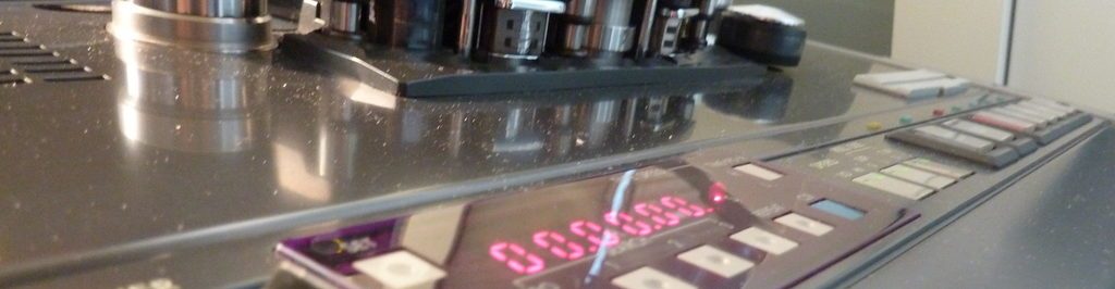


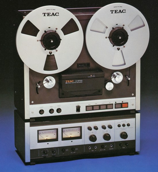
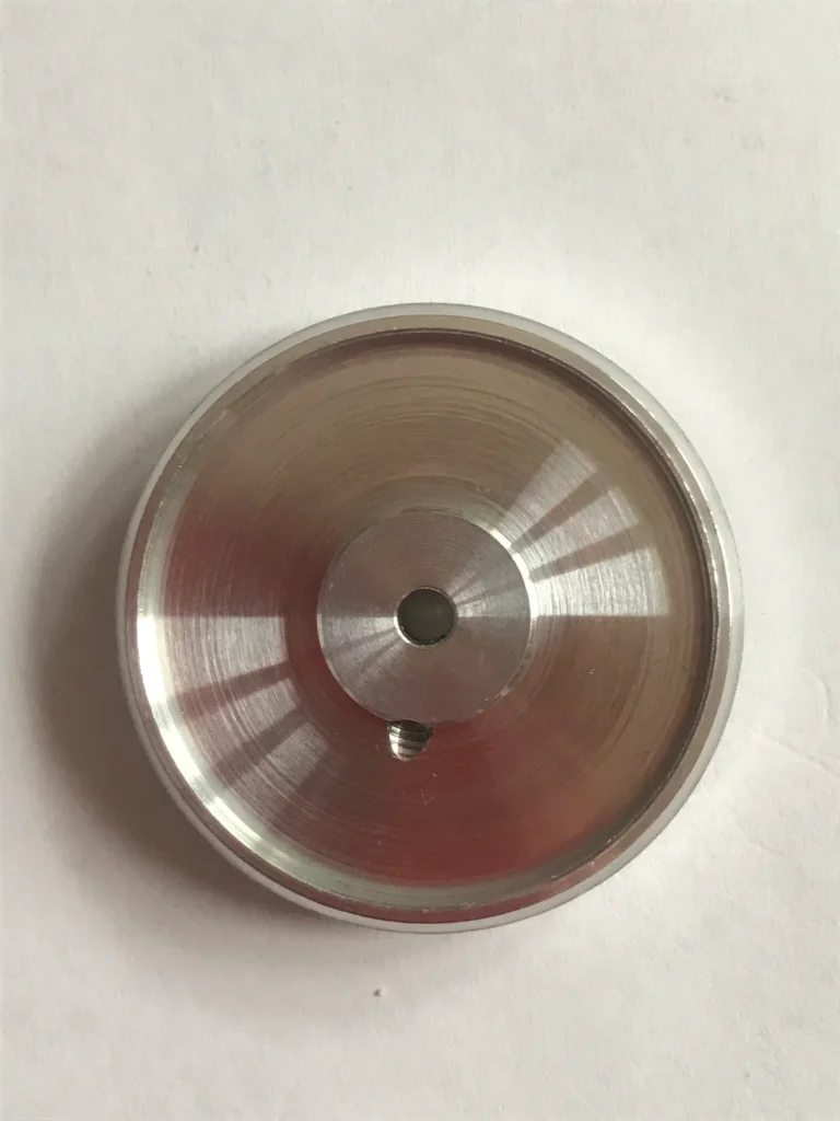
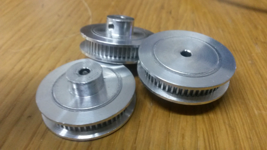
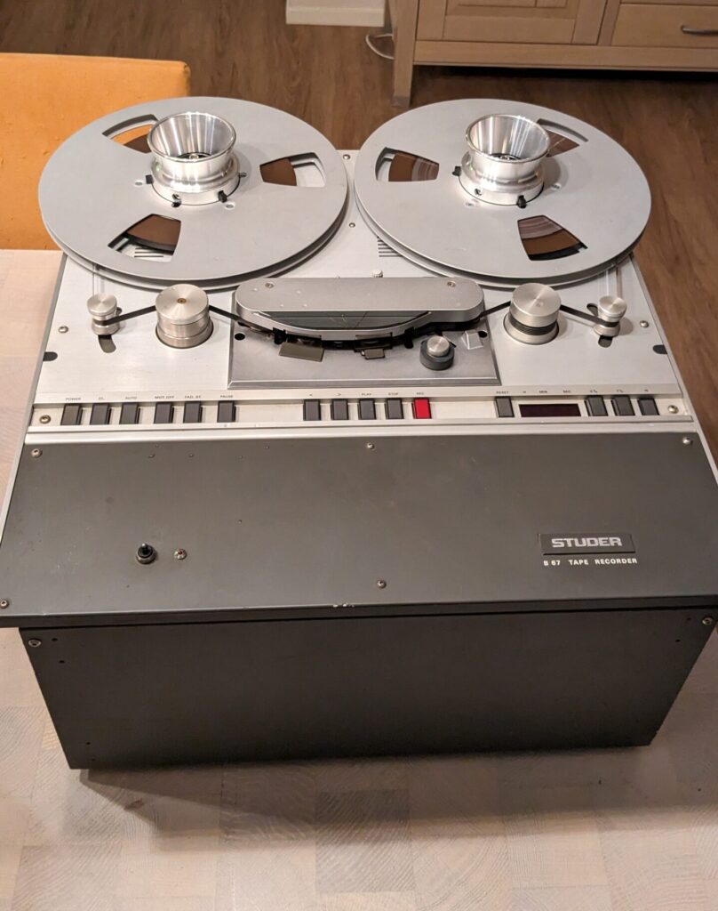
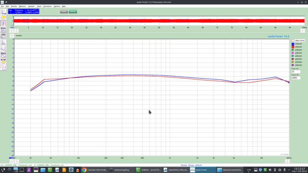

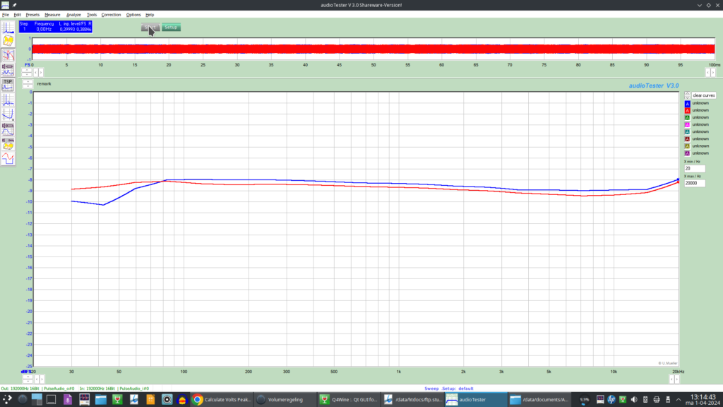
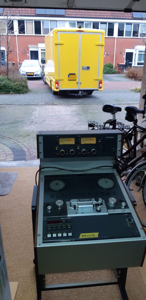
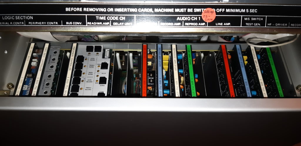
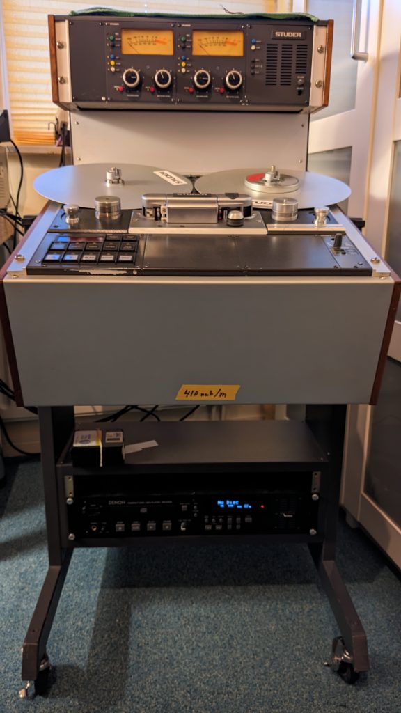
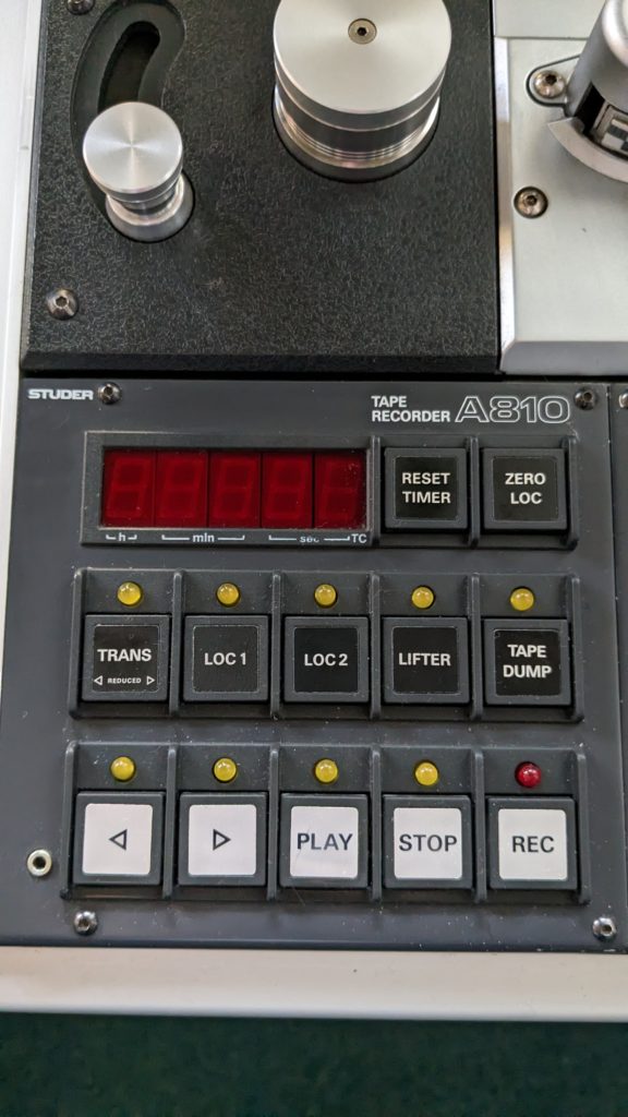
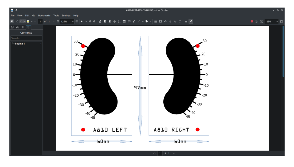
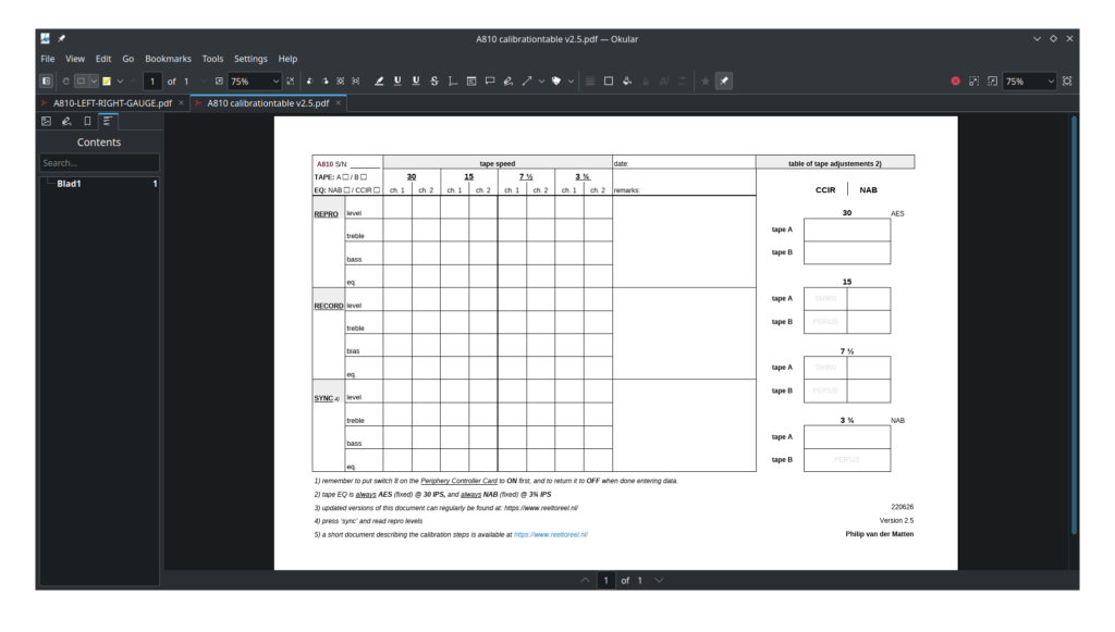
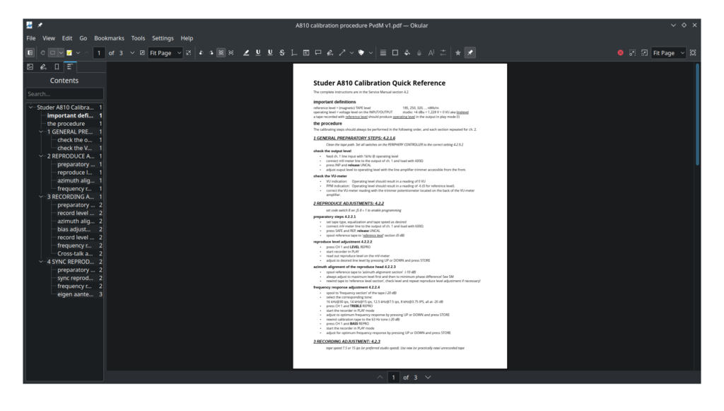
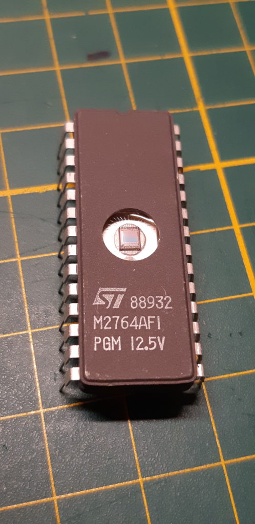
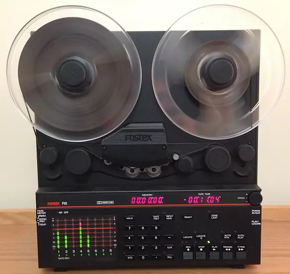
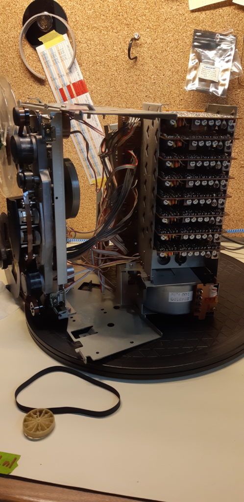
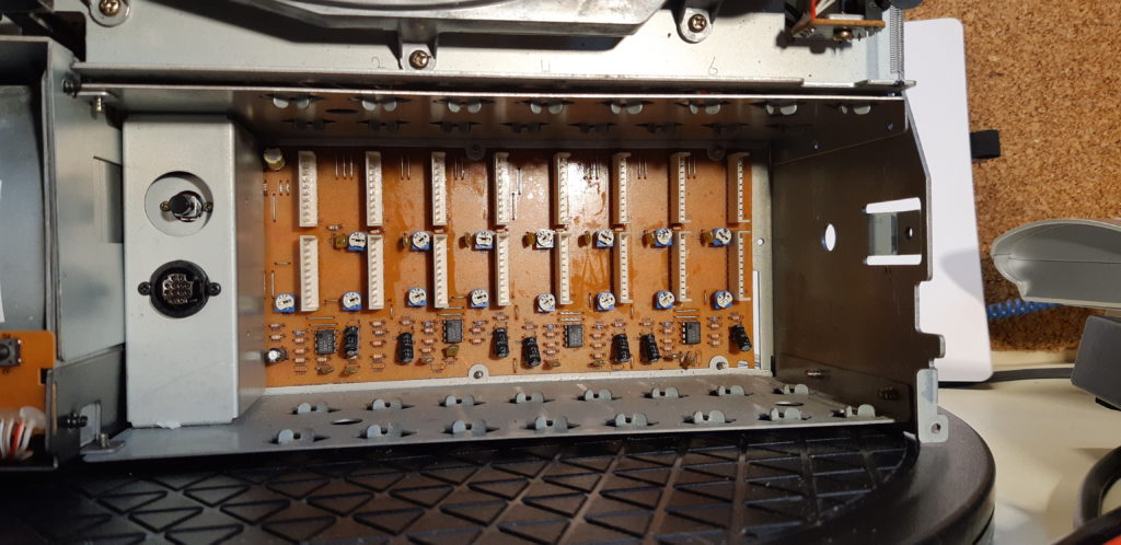
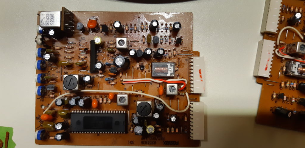
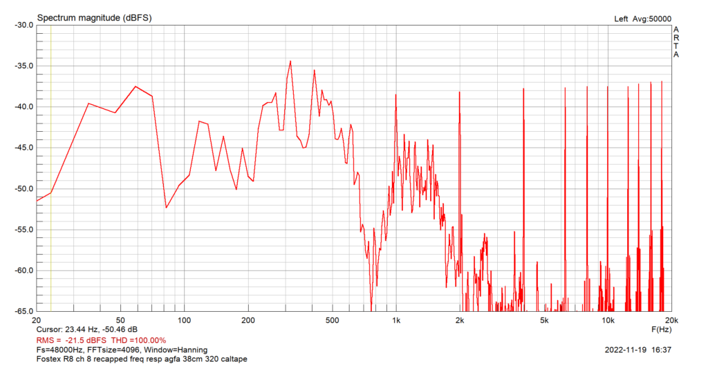
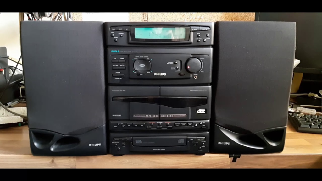
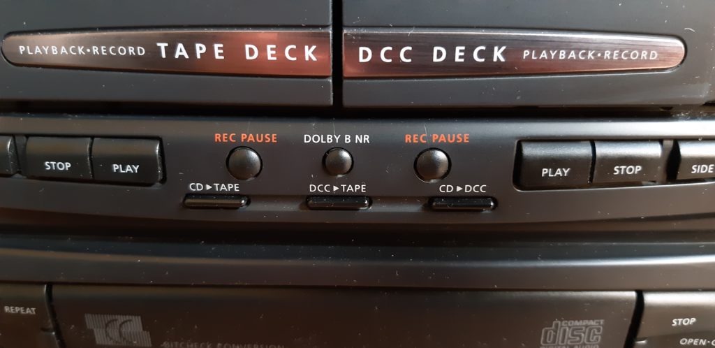
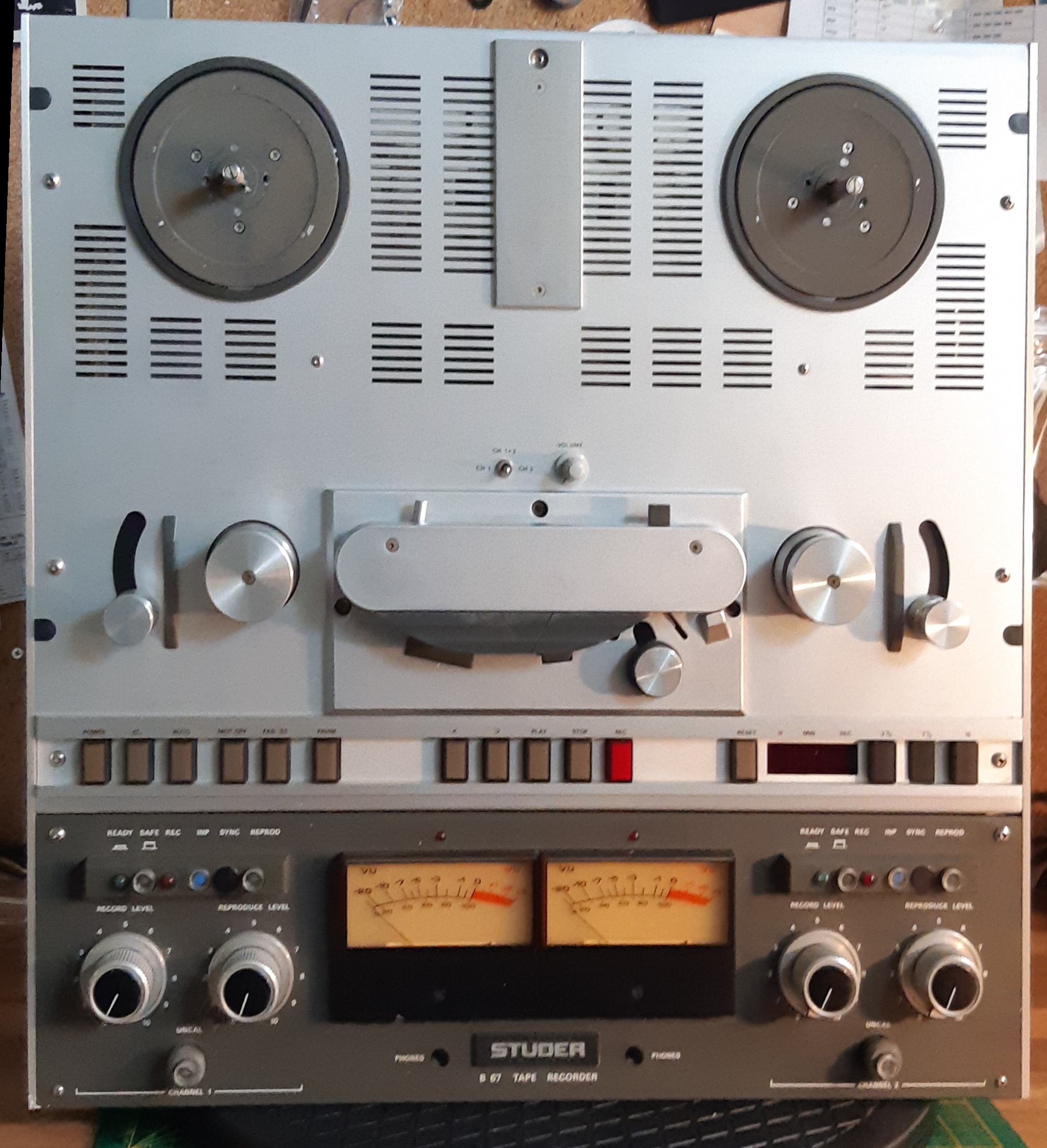
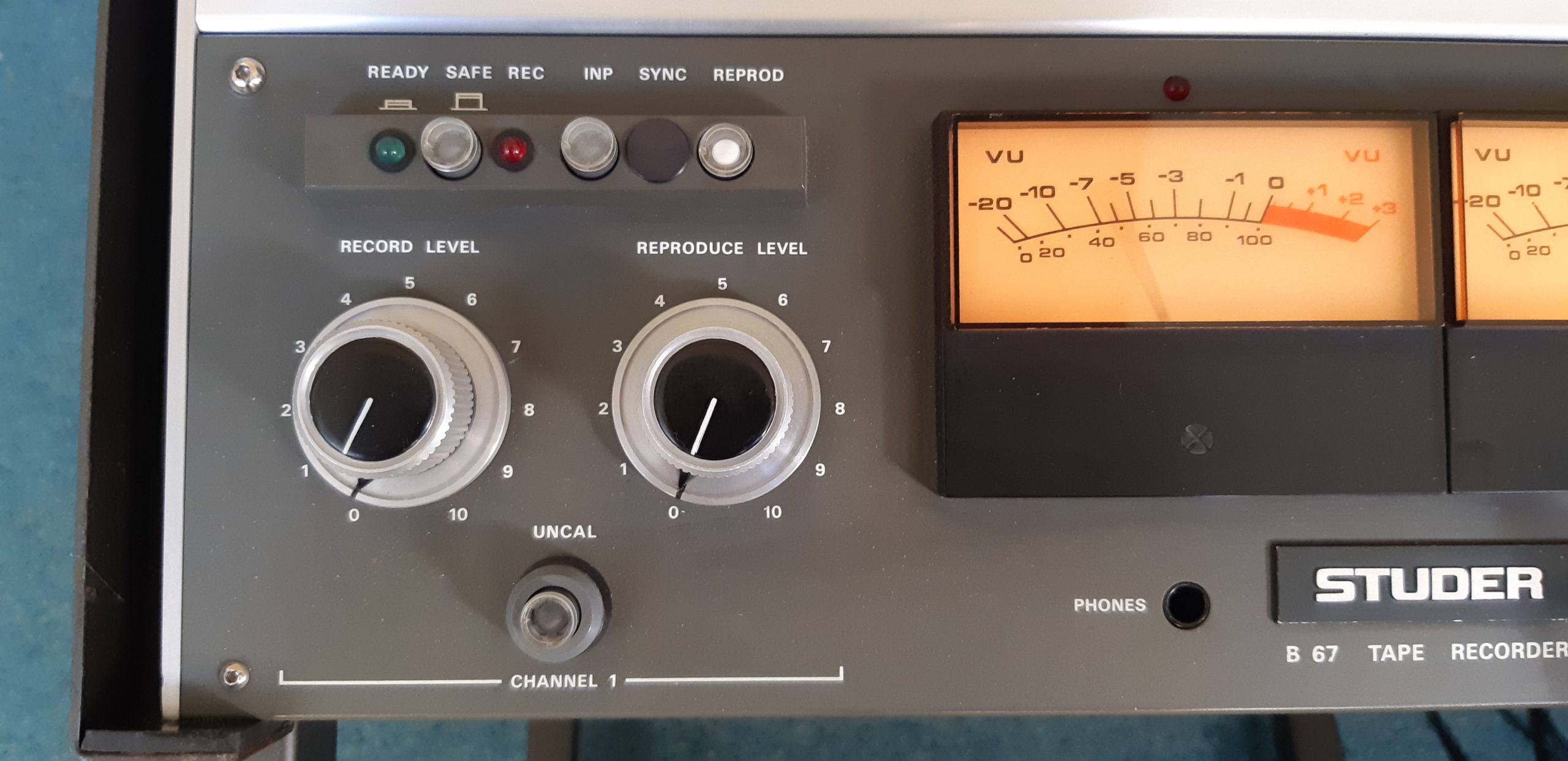
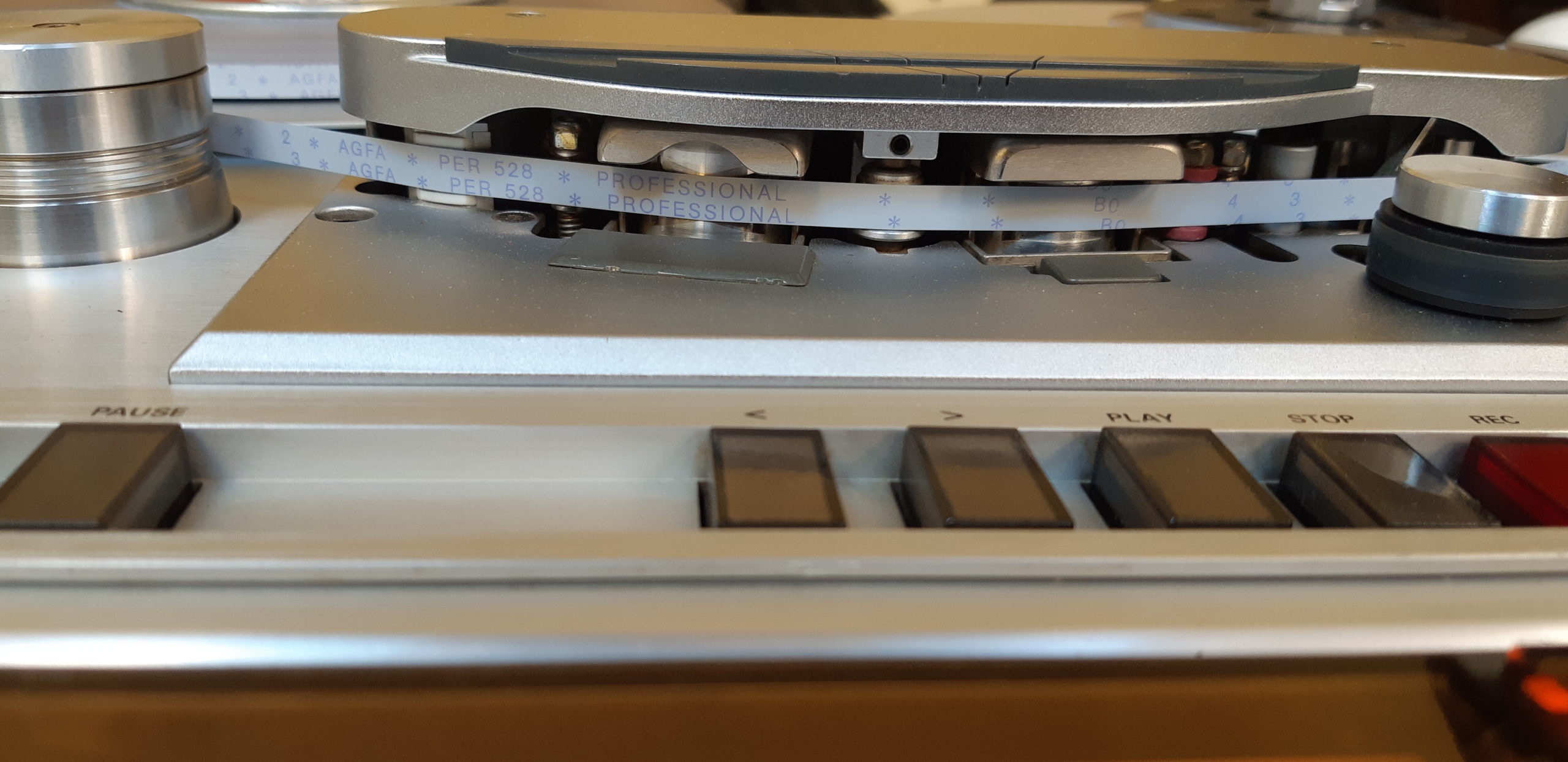
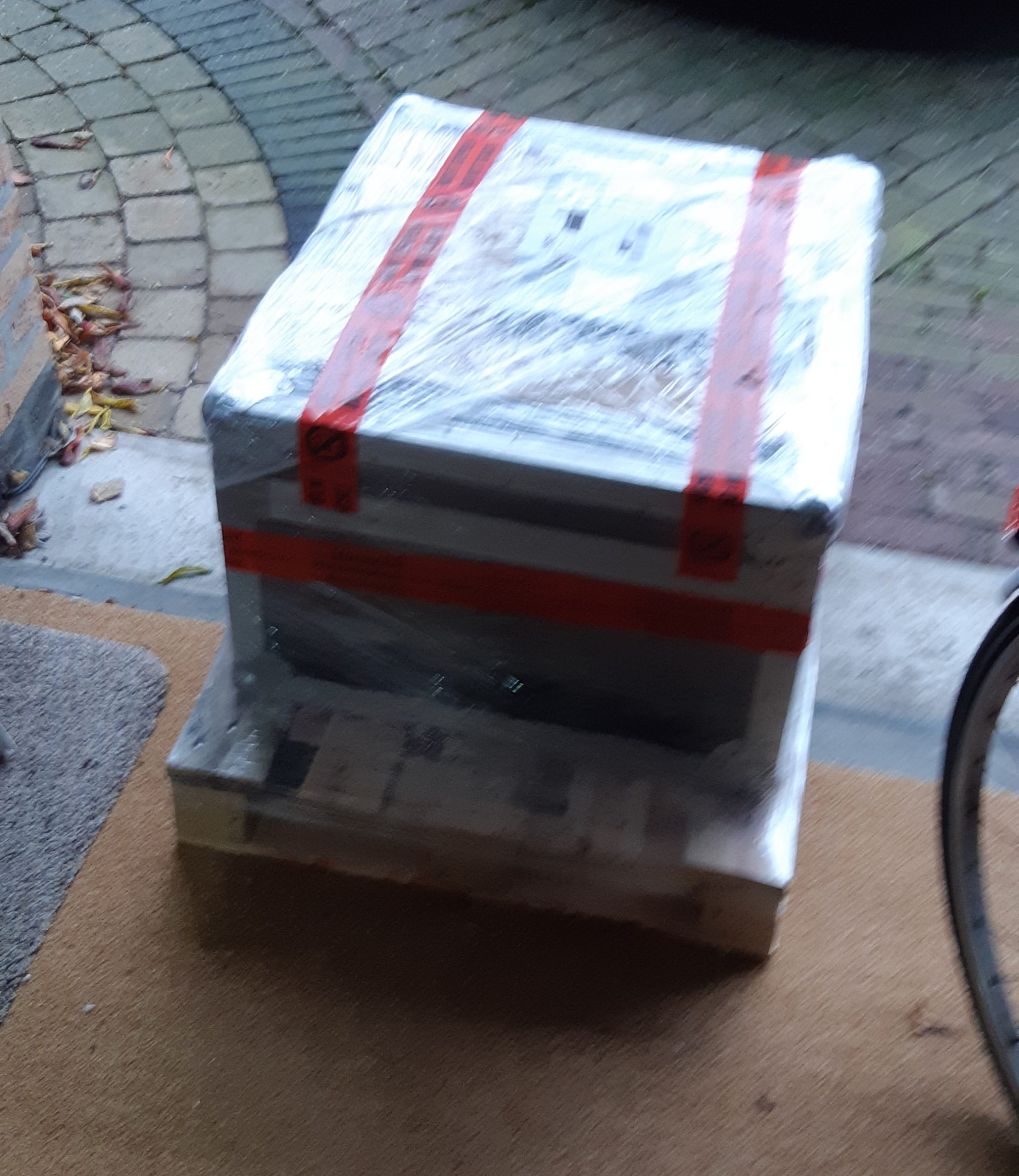
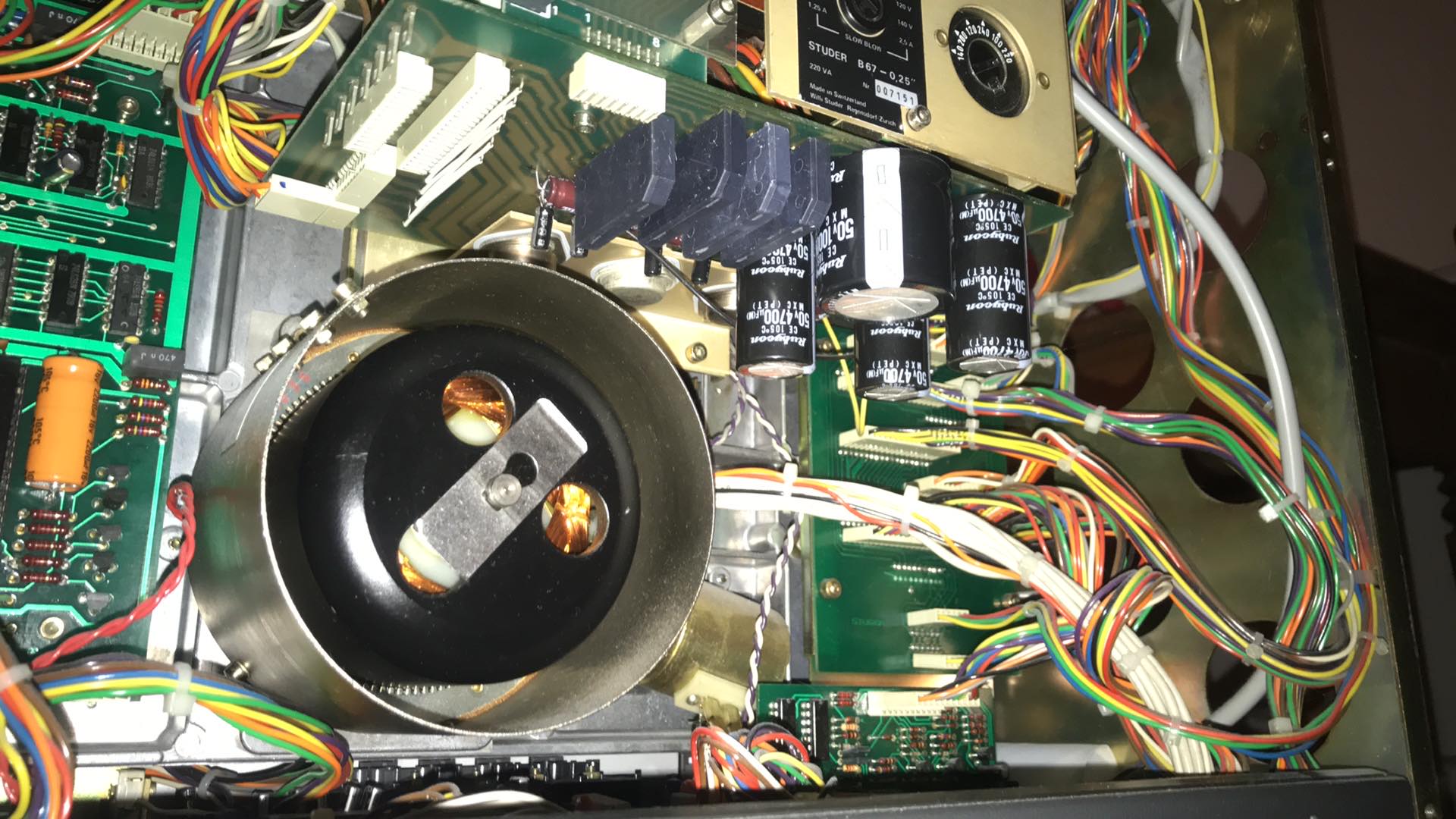
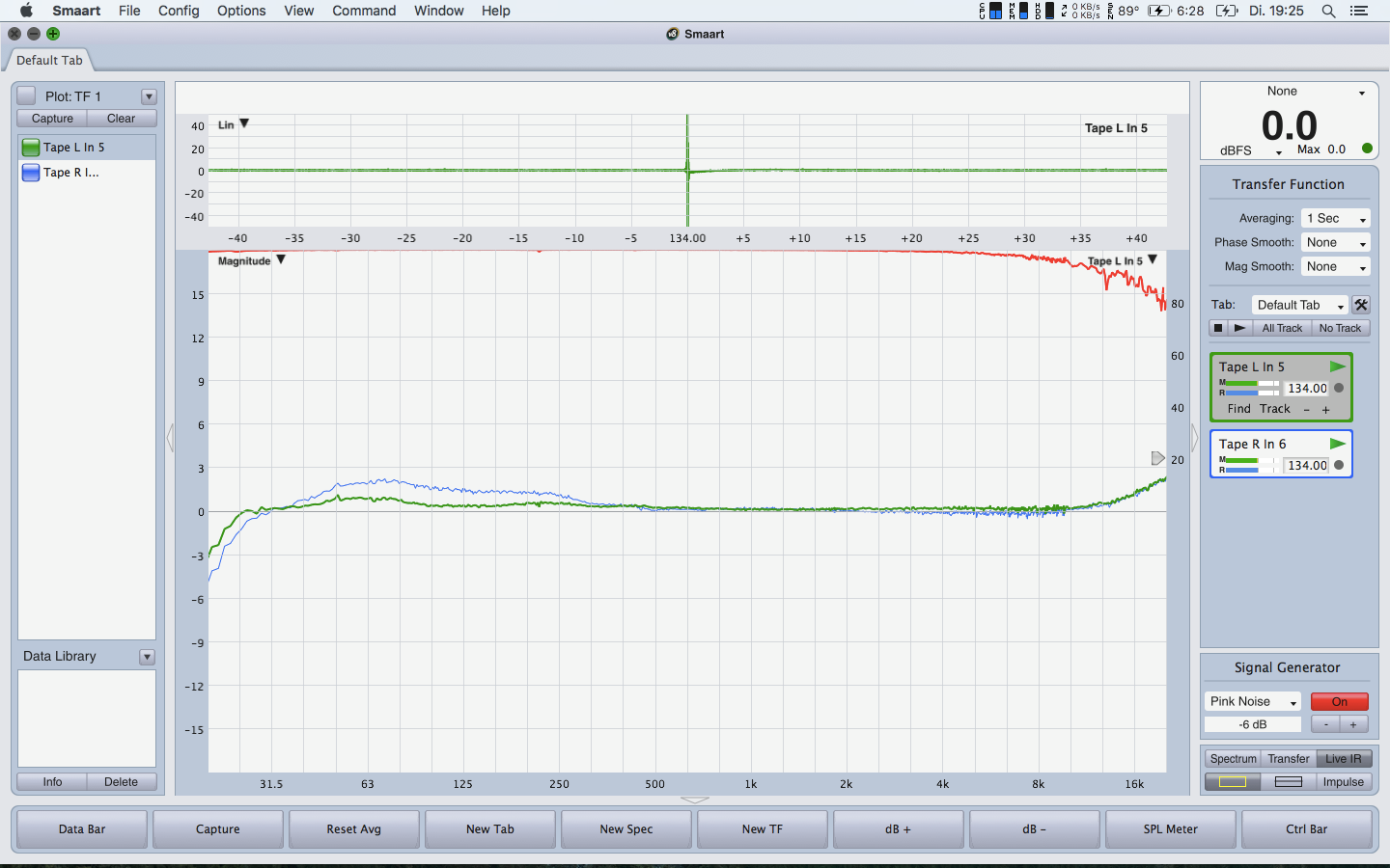
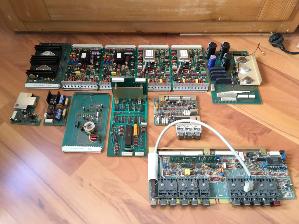
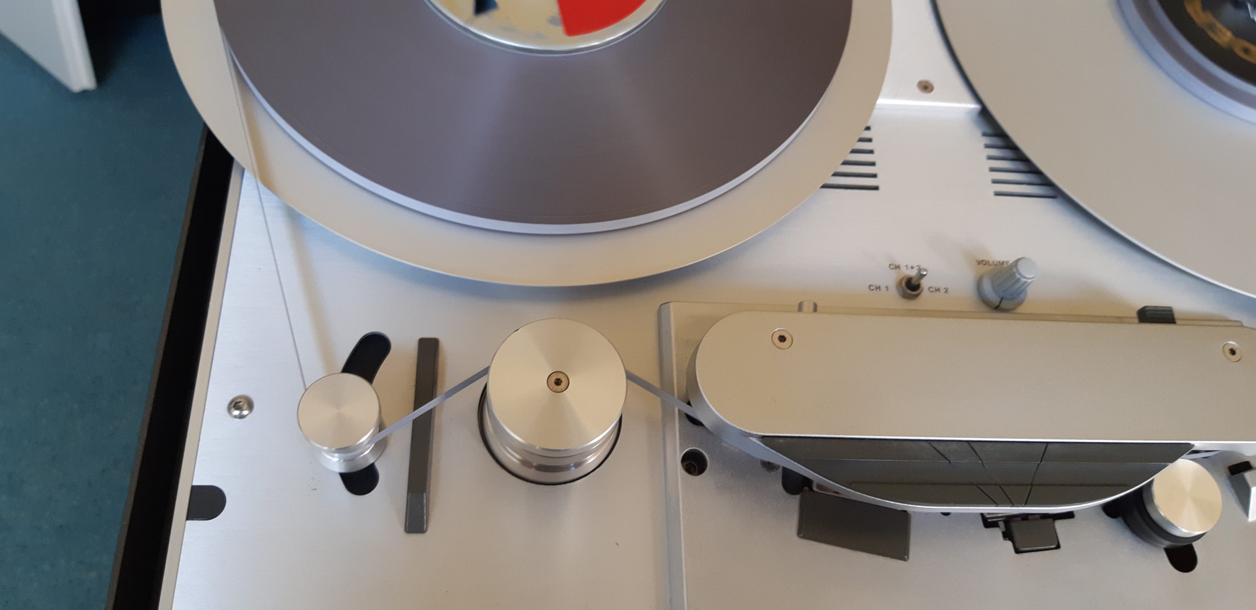
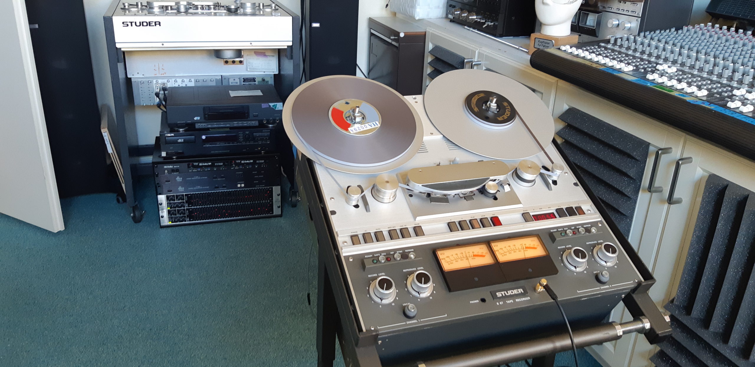
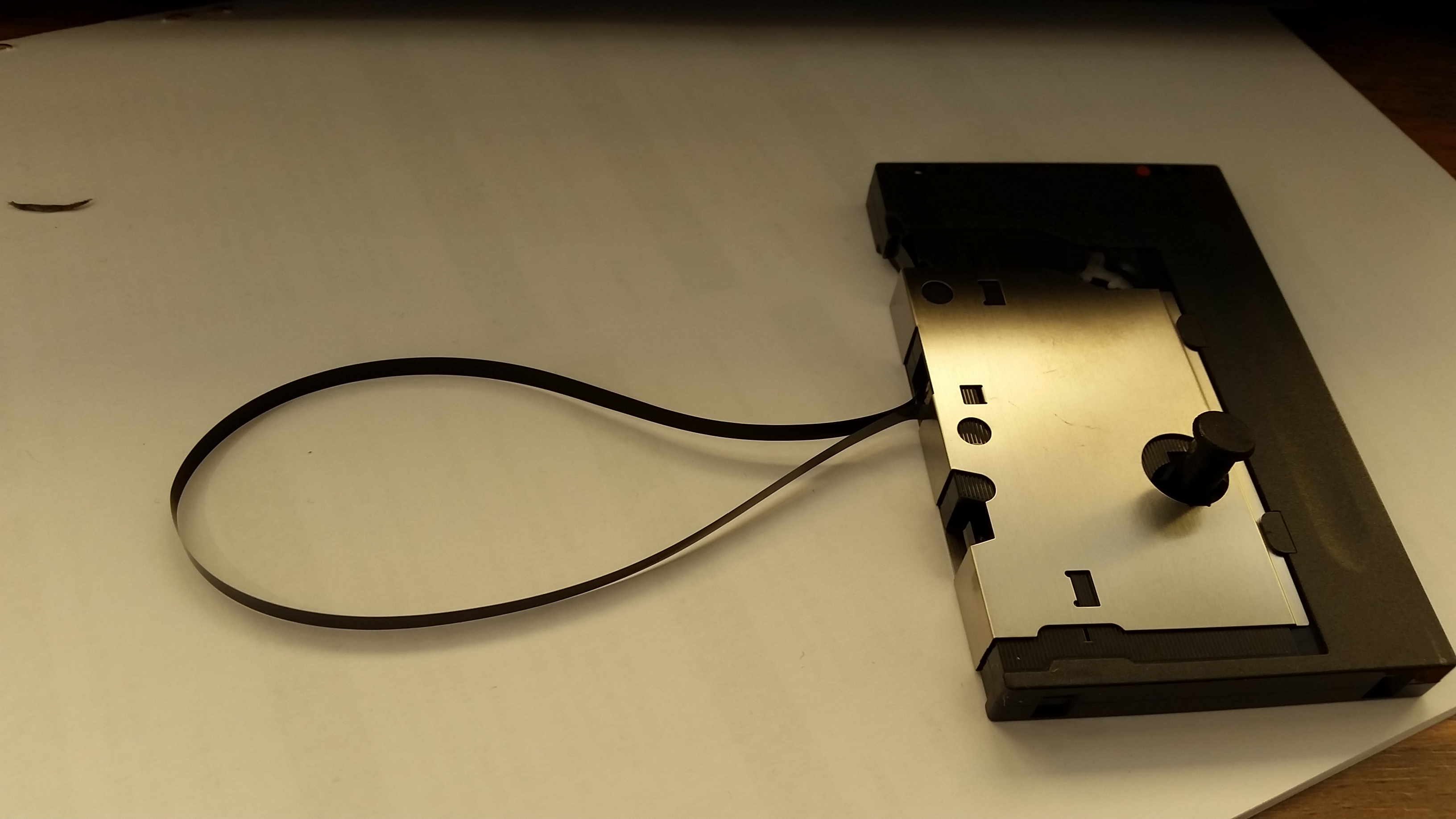
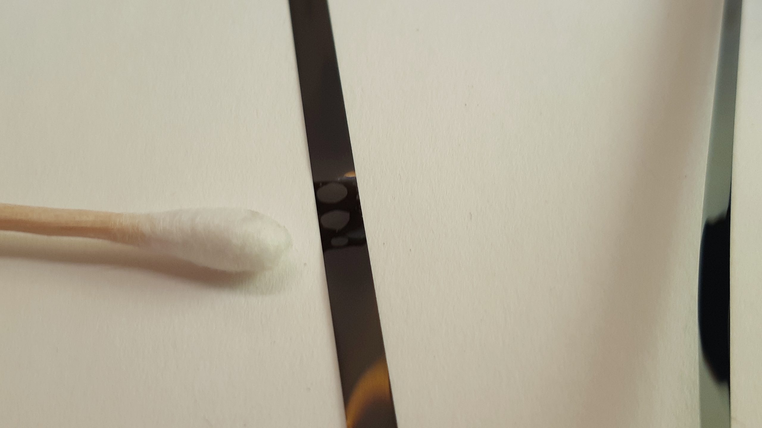
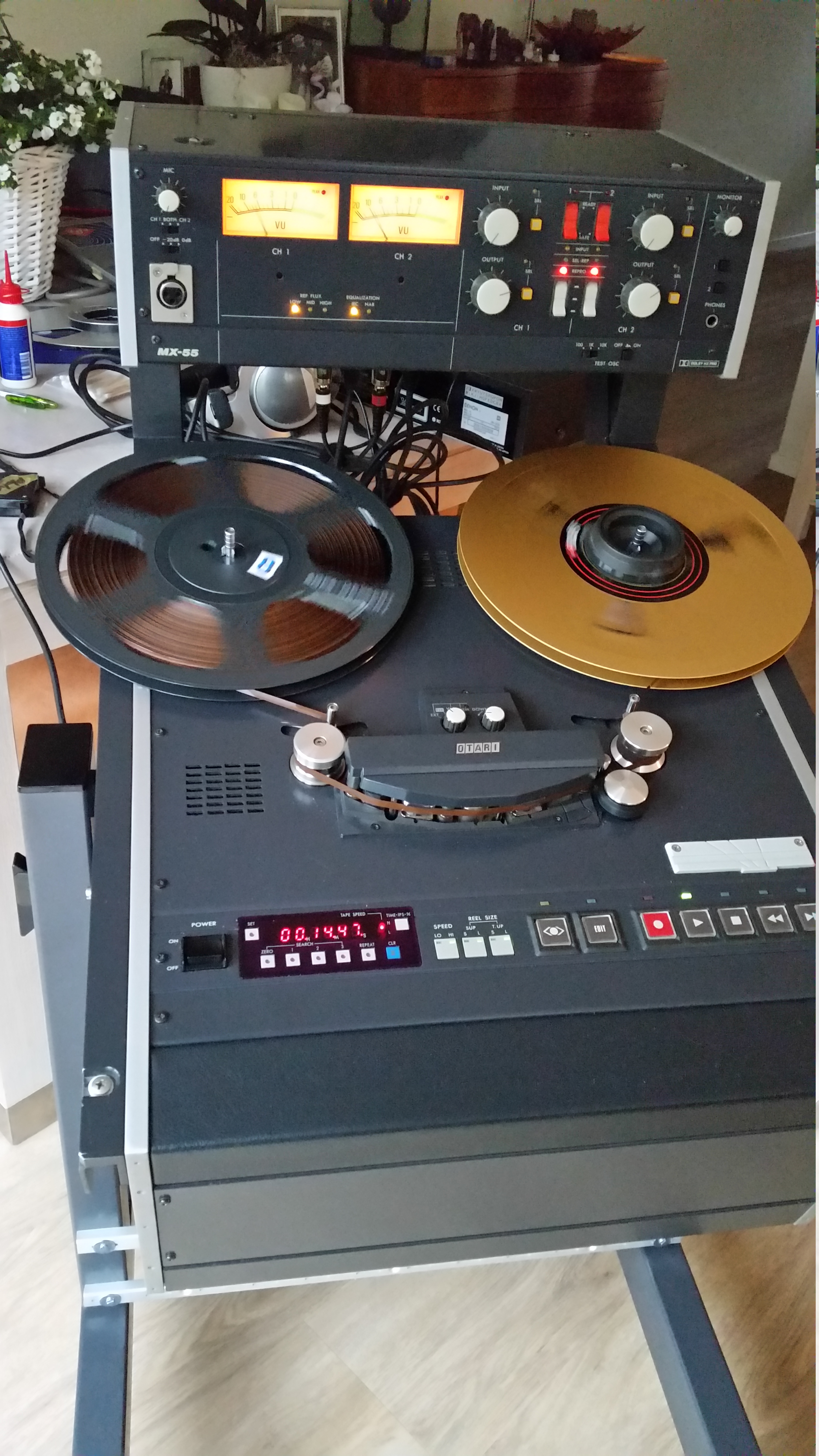
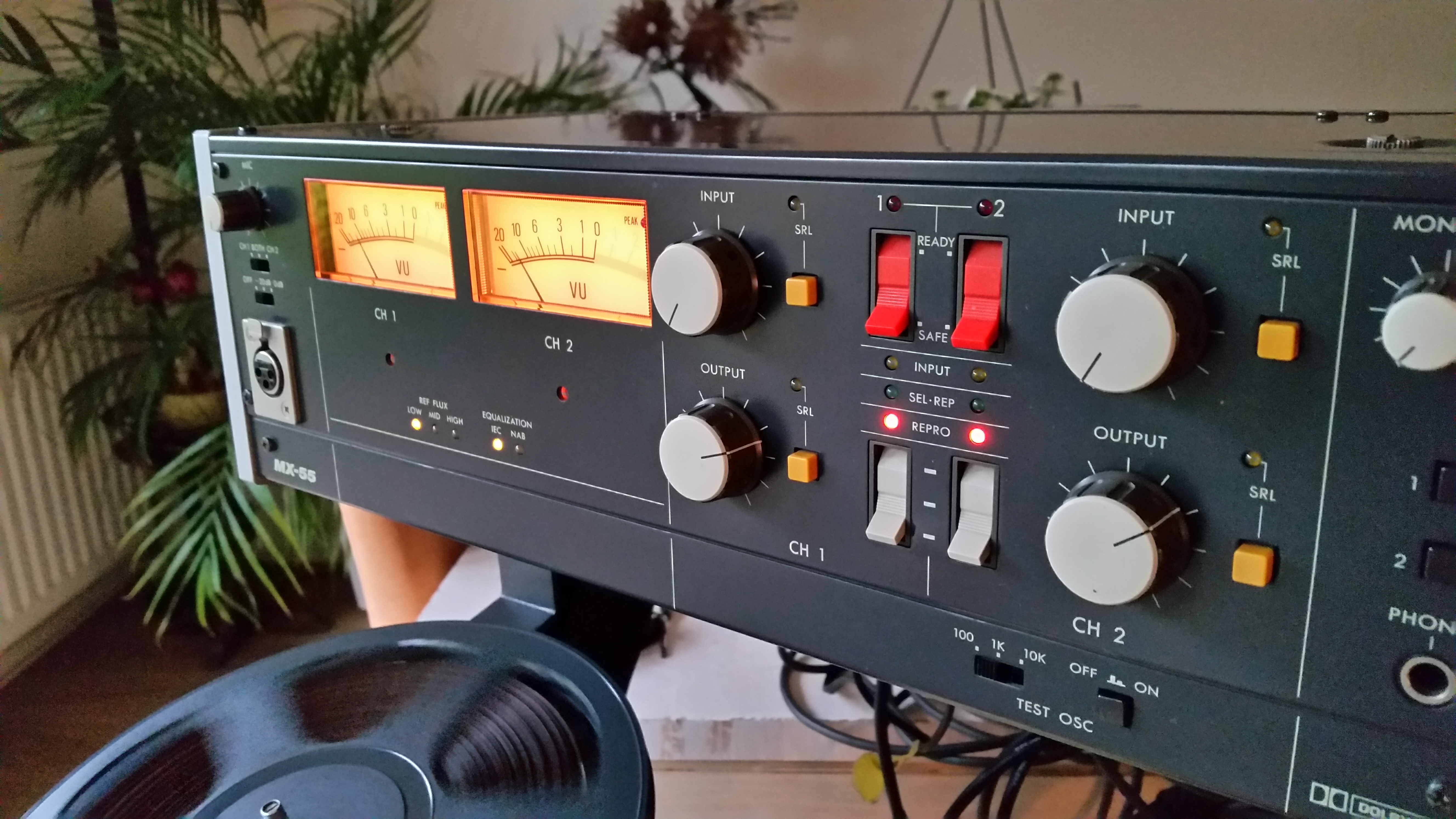
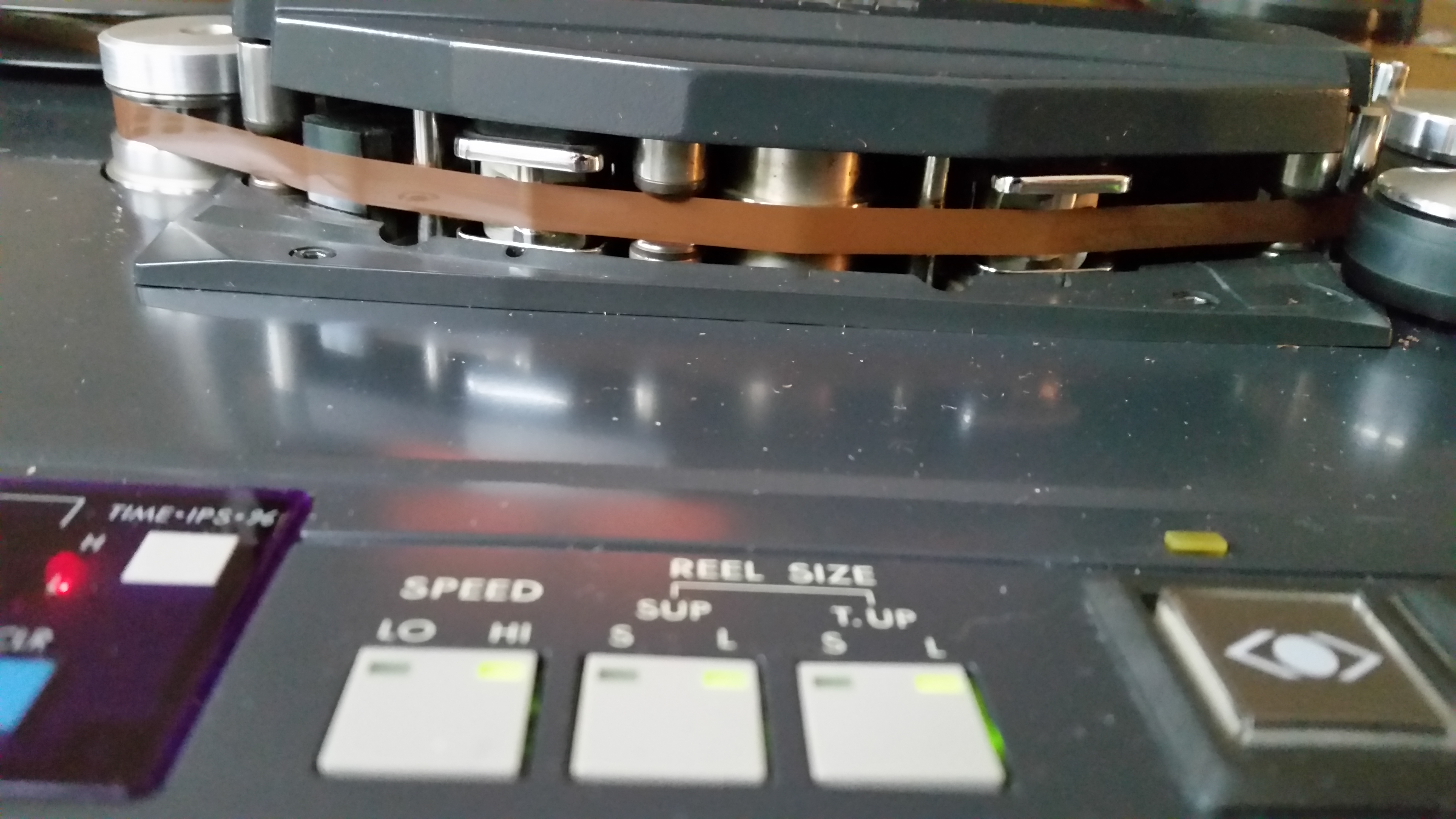
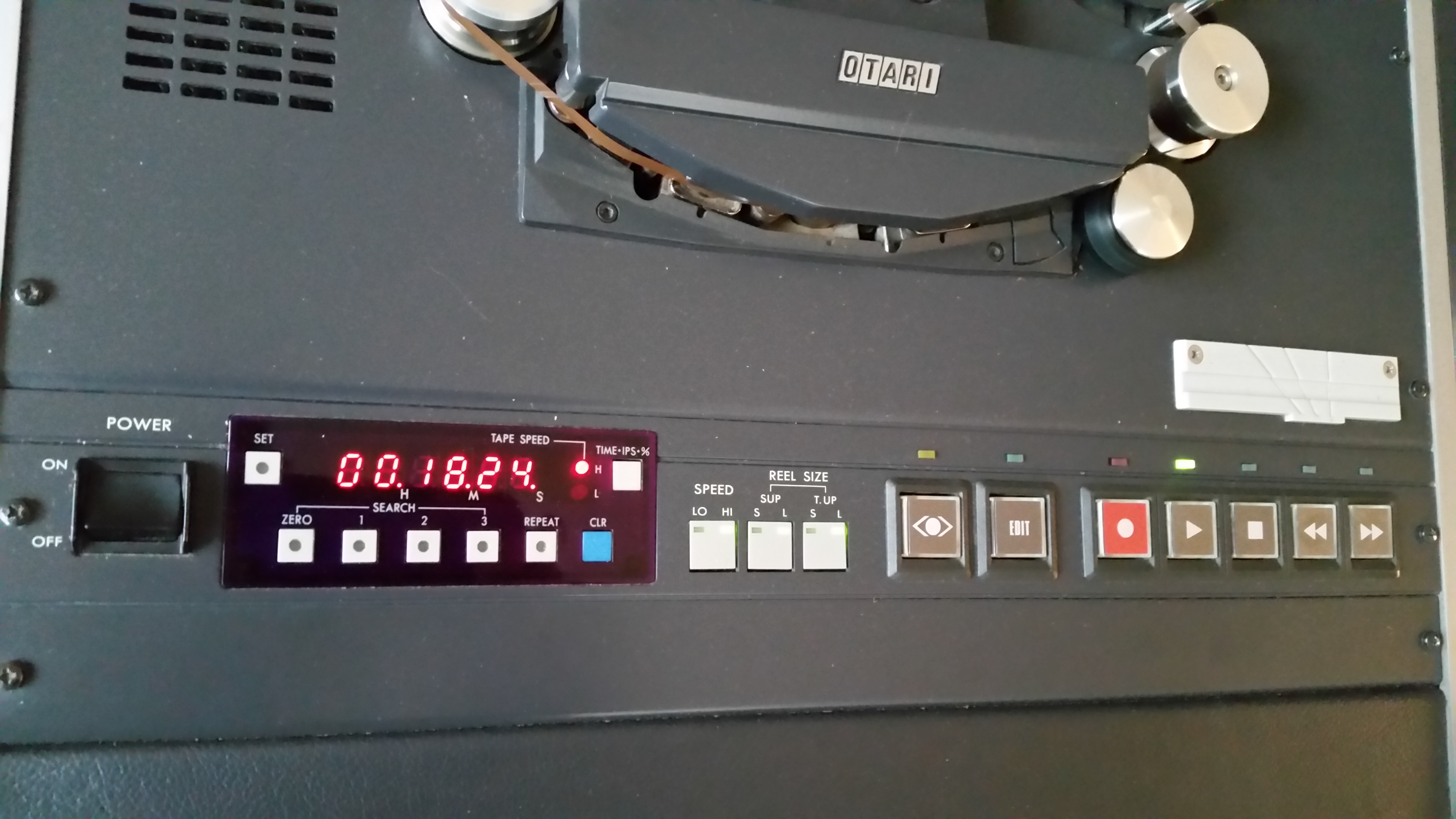
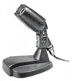
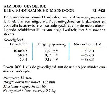
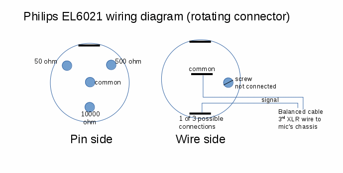
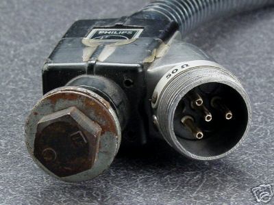

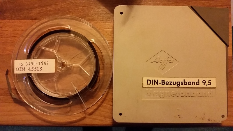


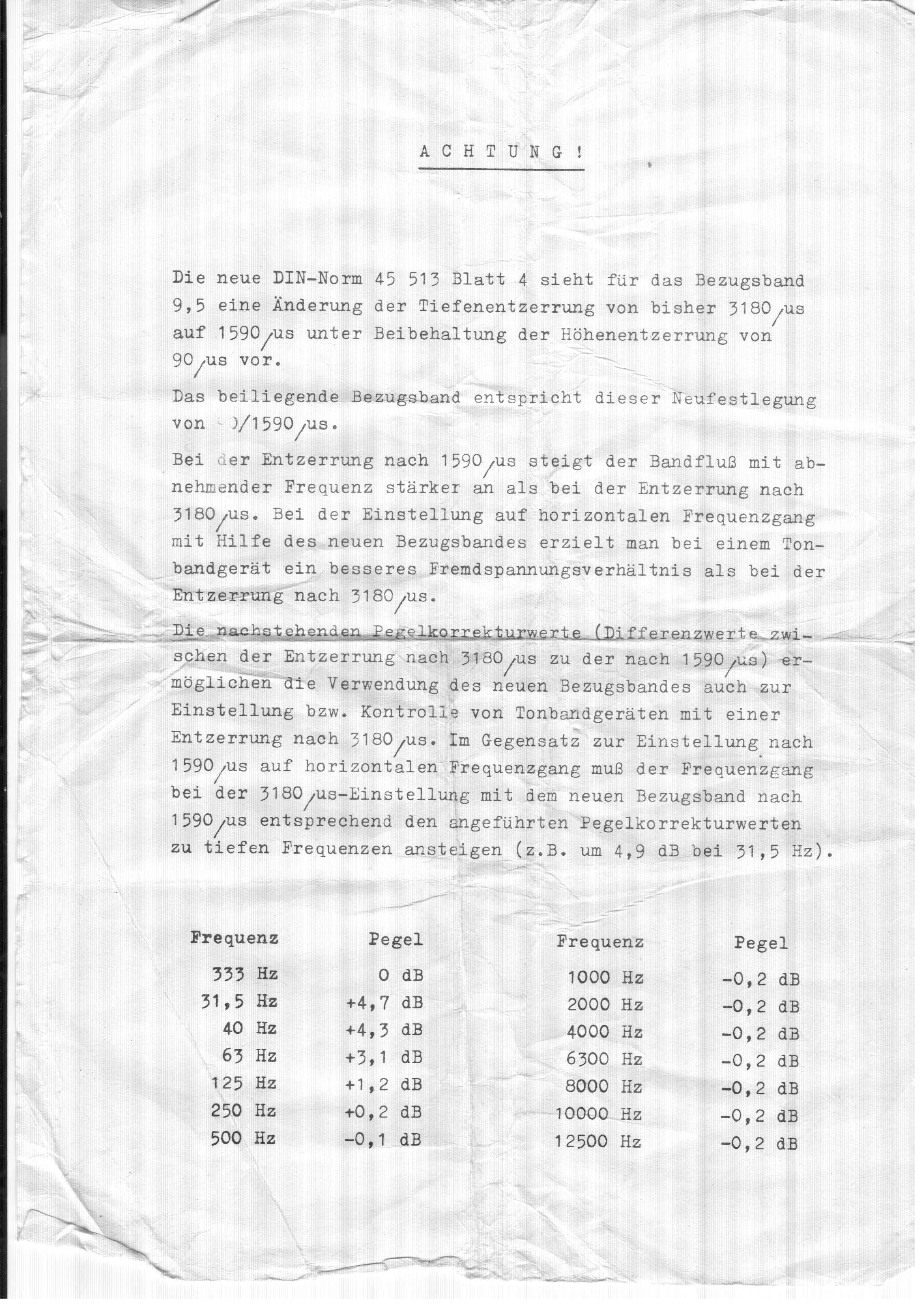
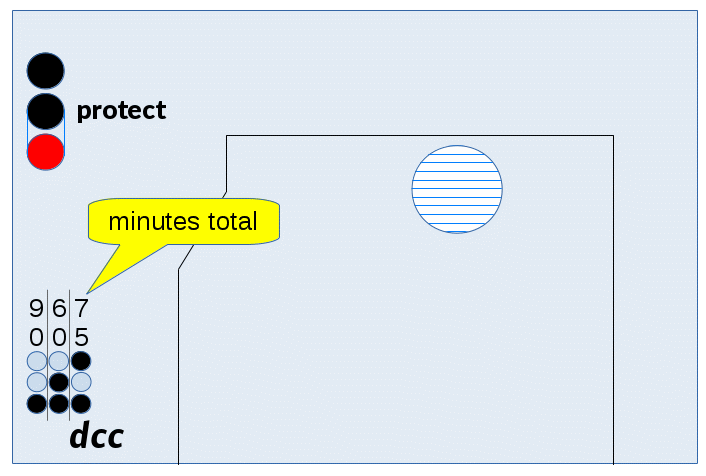
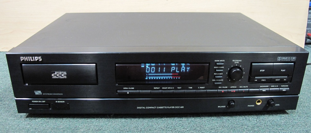
.jpg)

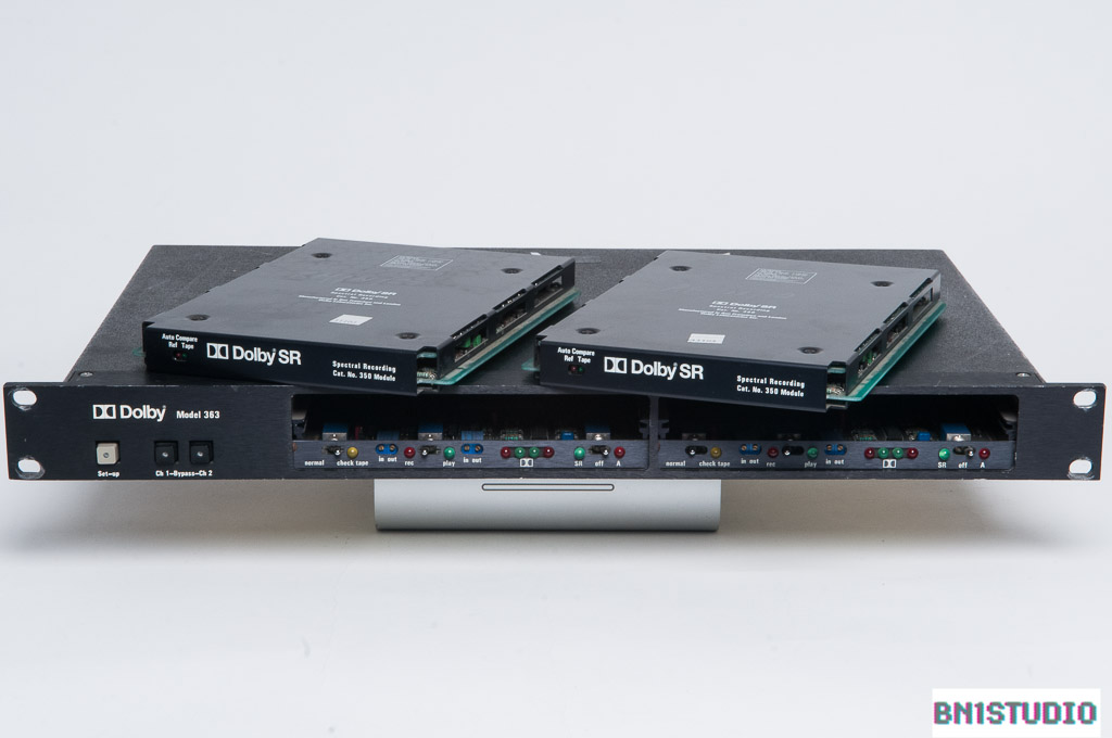

:format(jpeg):mode_rgb():quality(40)/discogs-images/R-1096544-1191762778.jpeg.jpg)
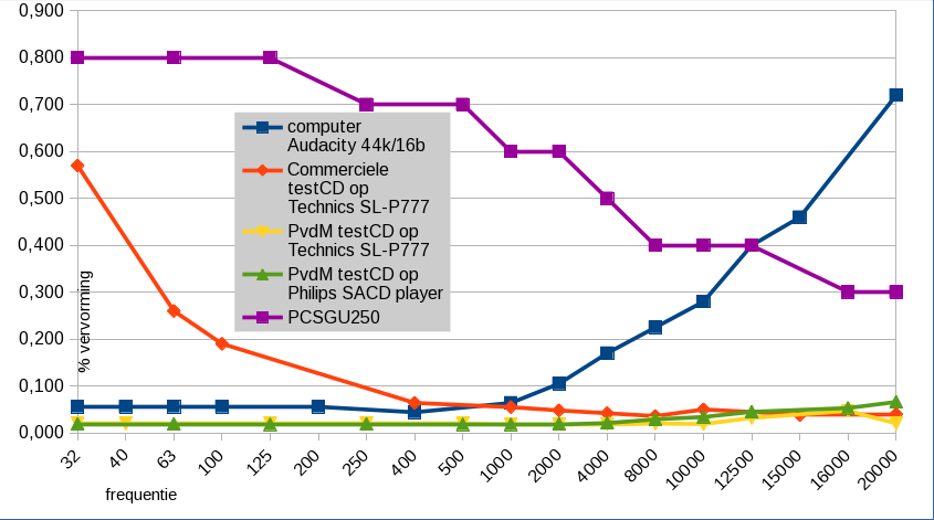
 To clean contacts in audio equipment, I do the following:
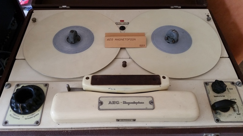
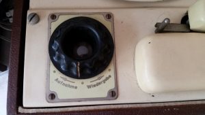
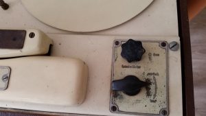
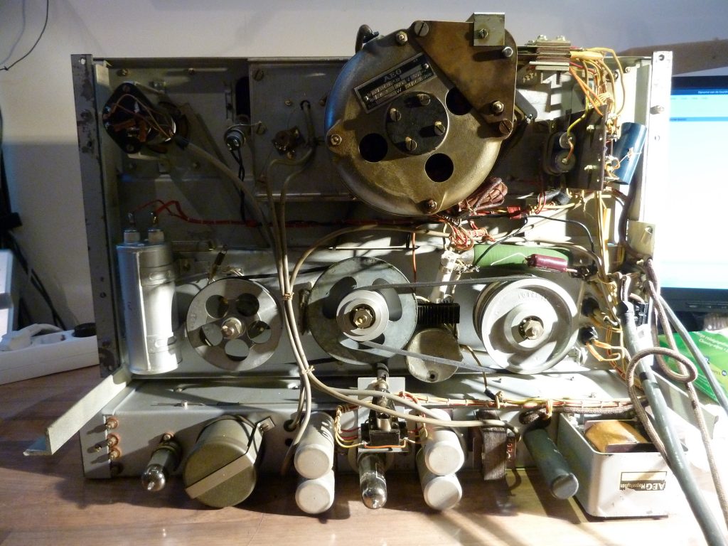
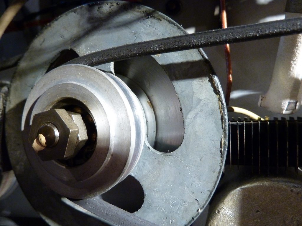
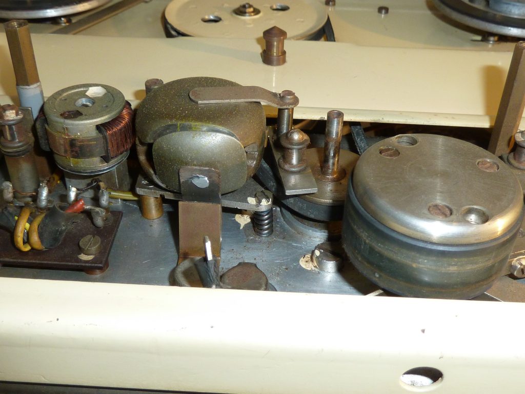
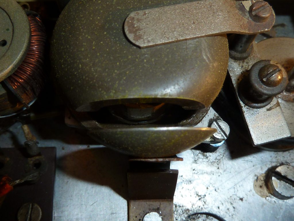
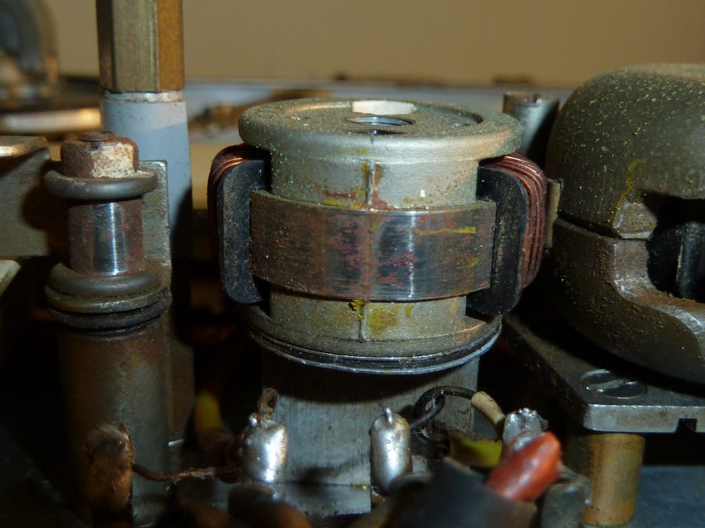
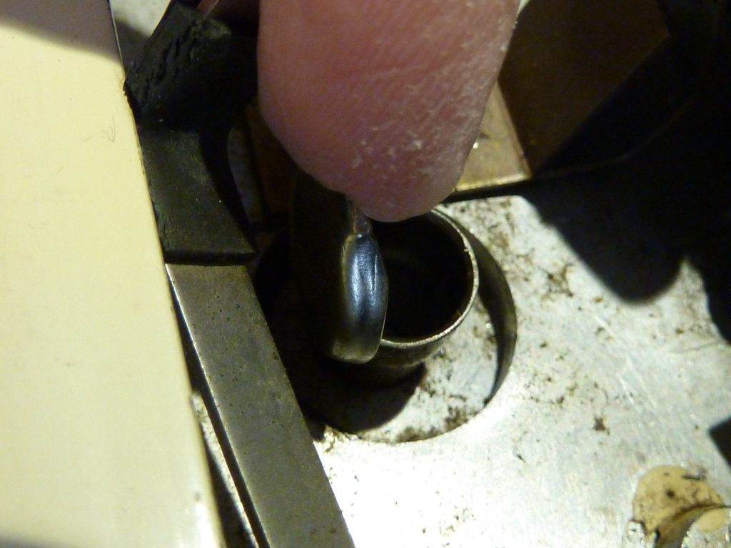
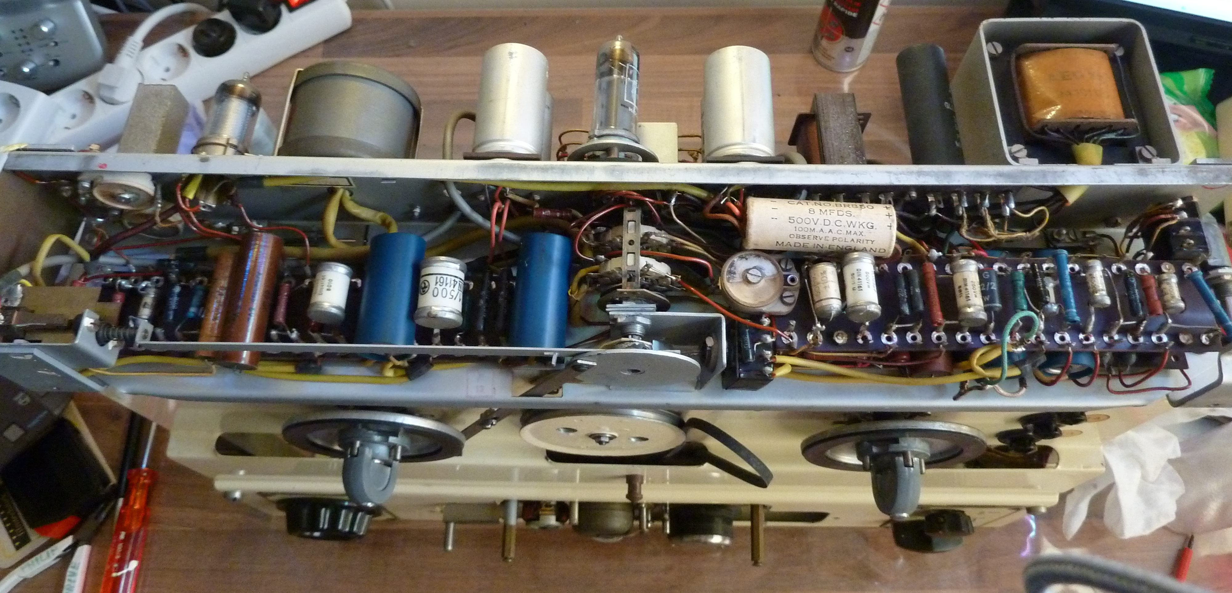
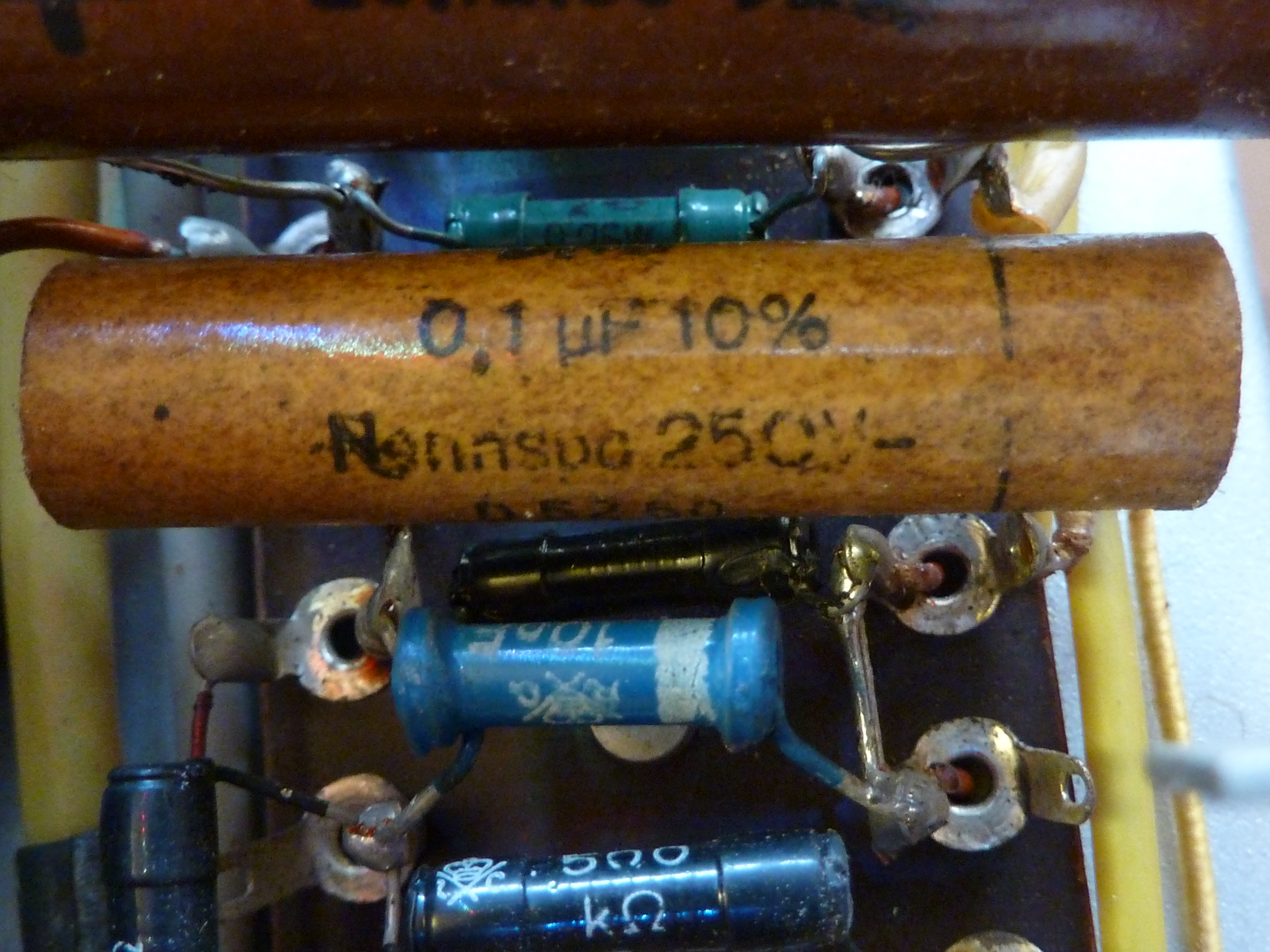
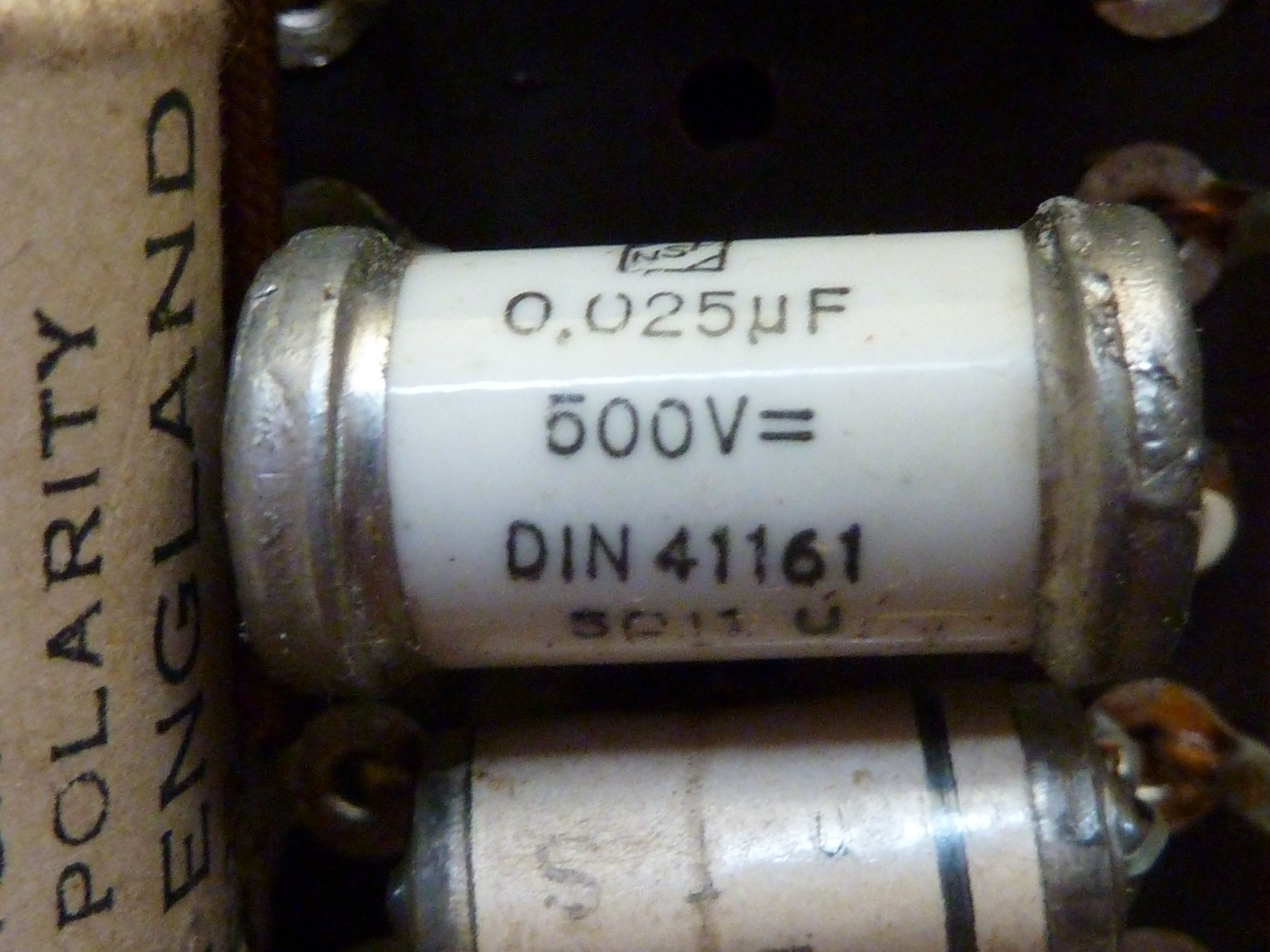
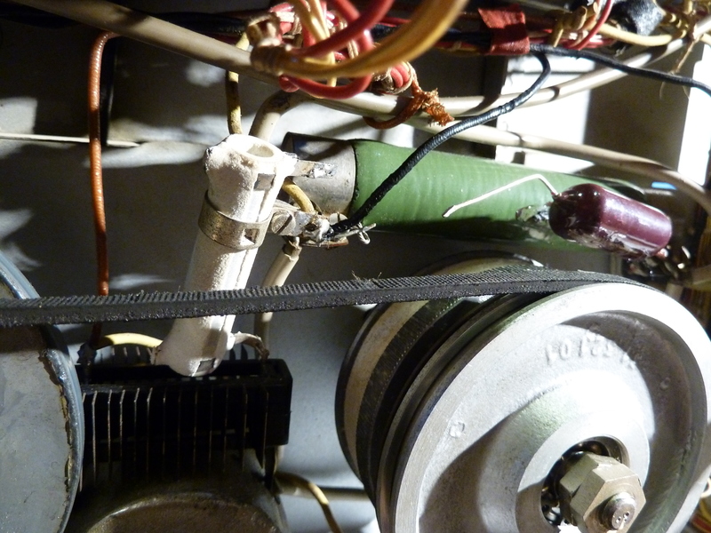
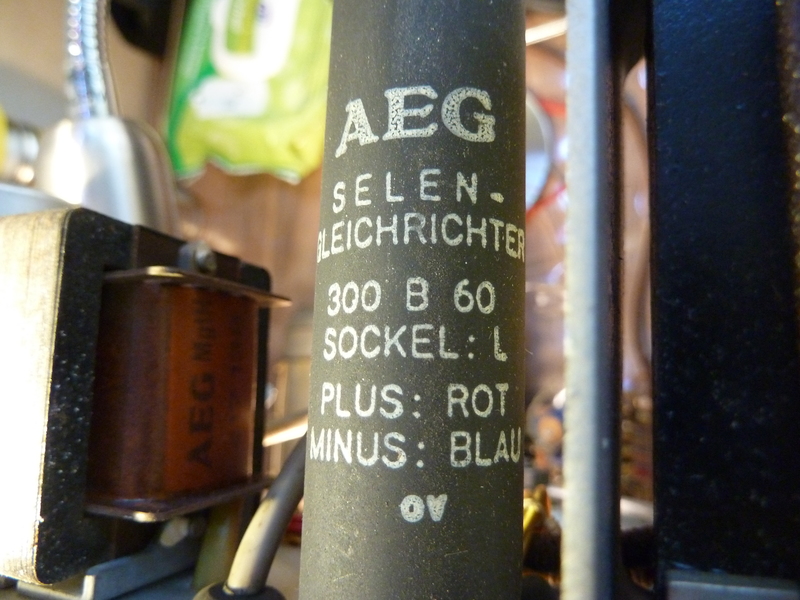
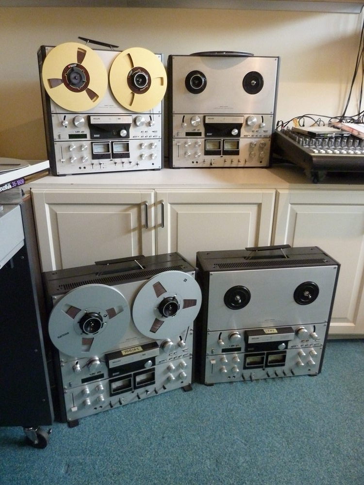
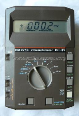 which is capable of measuring the frequency of a tone, when I thought it would be cool to use that meter to measure the 1kHz tone which is a the beginning of my (generic) calibration tapes. If the tape runs too fast, the measured frequency would be over 1000Hz, and if the speed was too low, it would be under 1000Hz. Suddenly I was fascinated by the fact whether my decks were running at the exact speed or not, or if not, how much deviation it had.
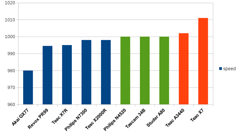
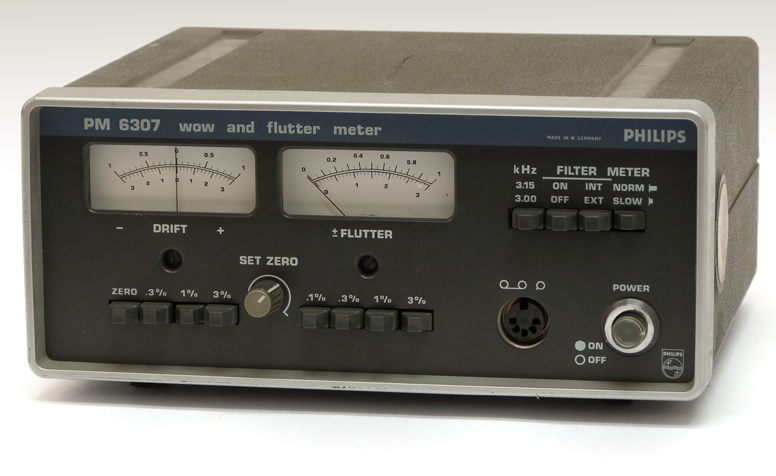
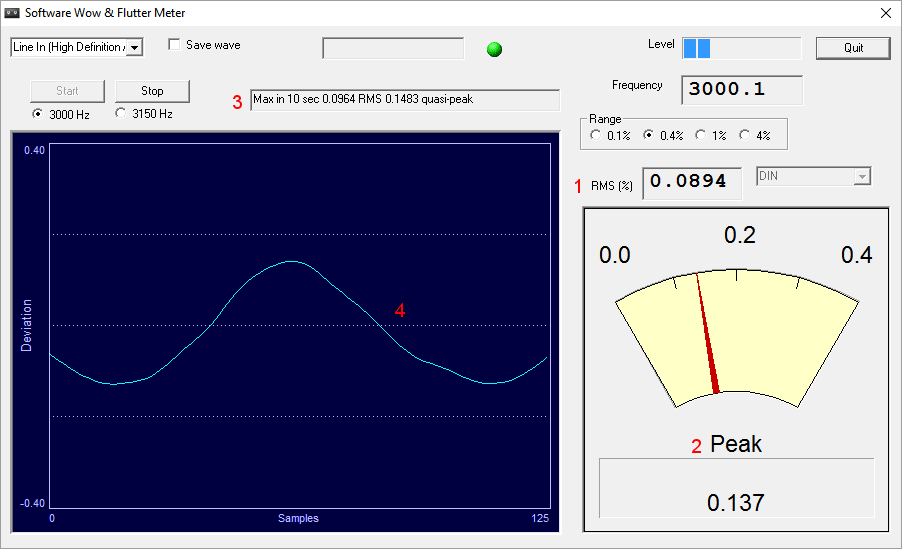

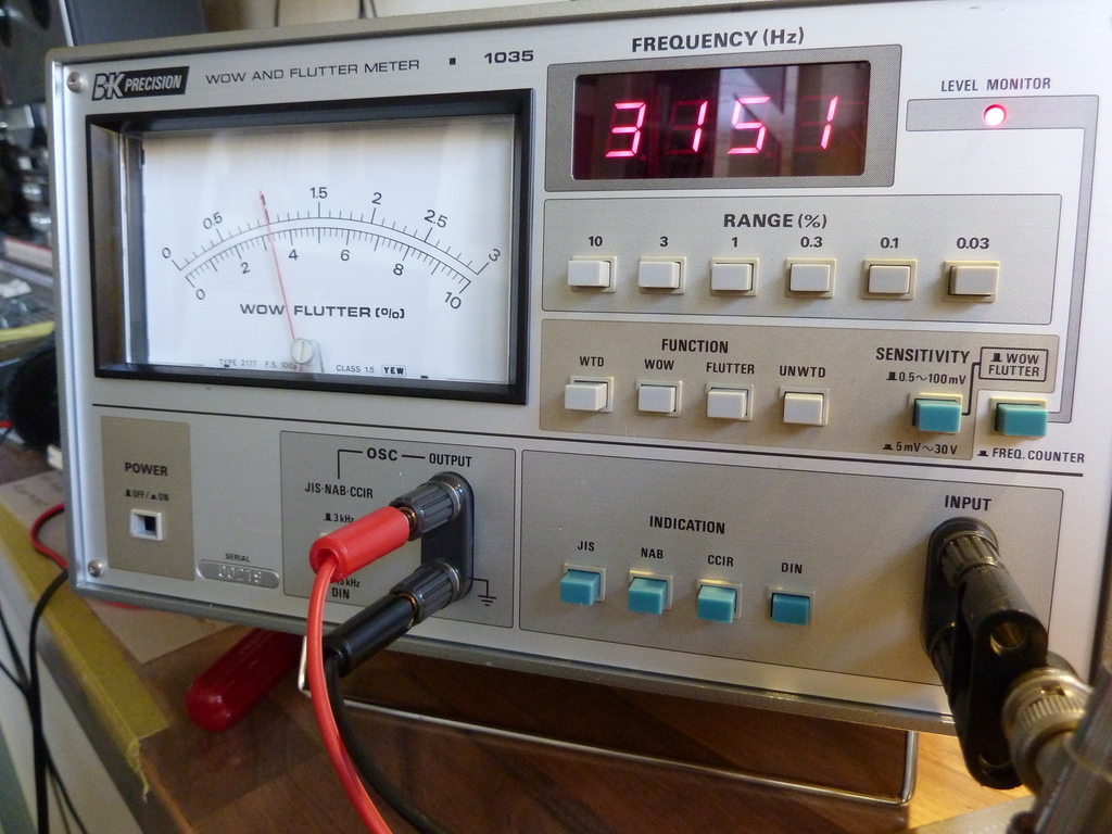
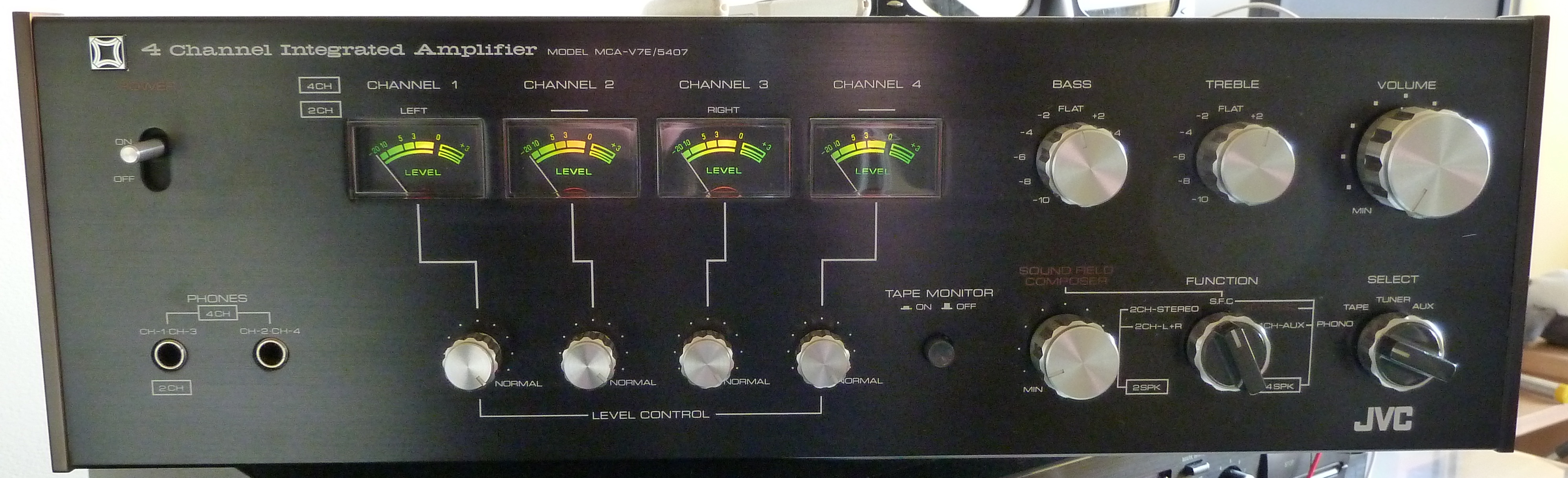
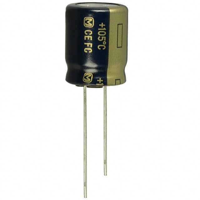
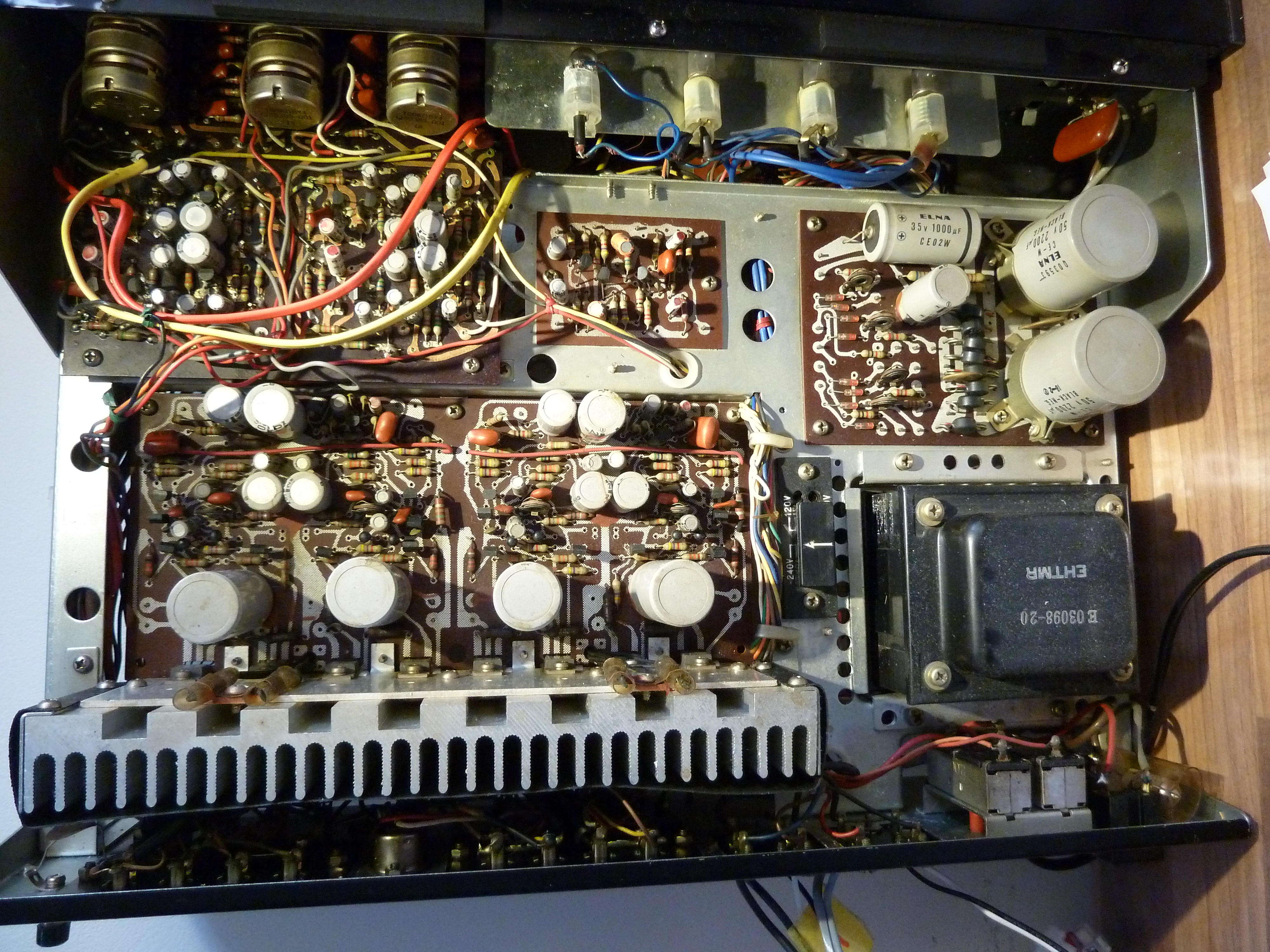
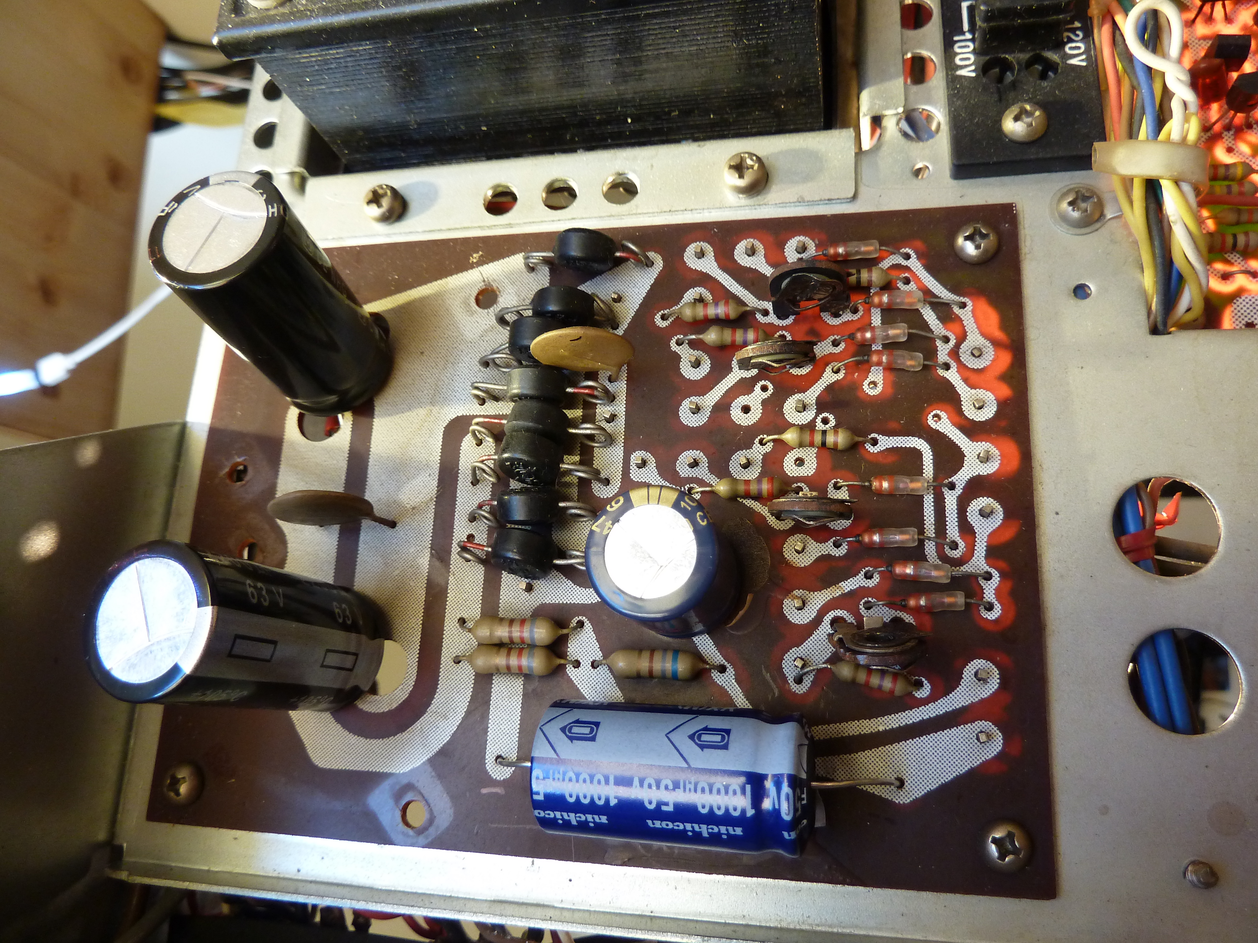
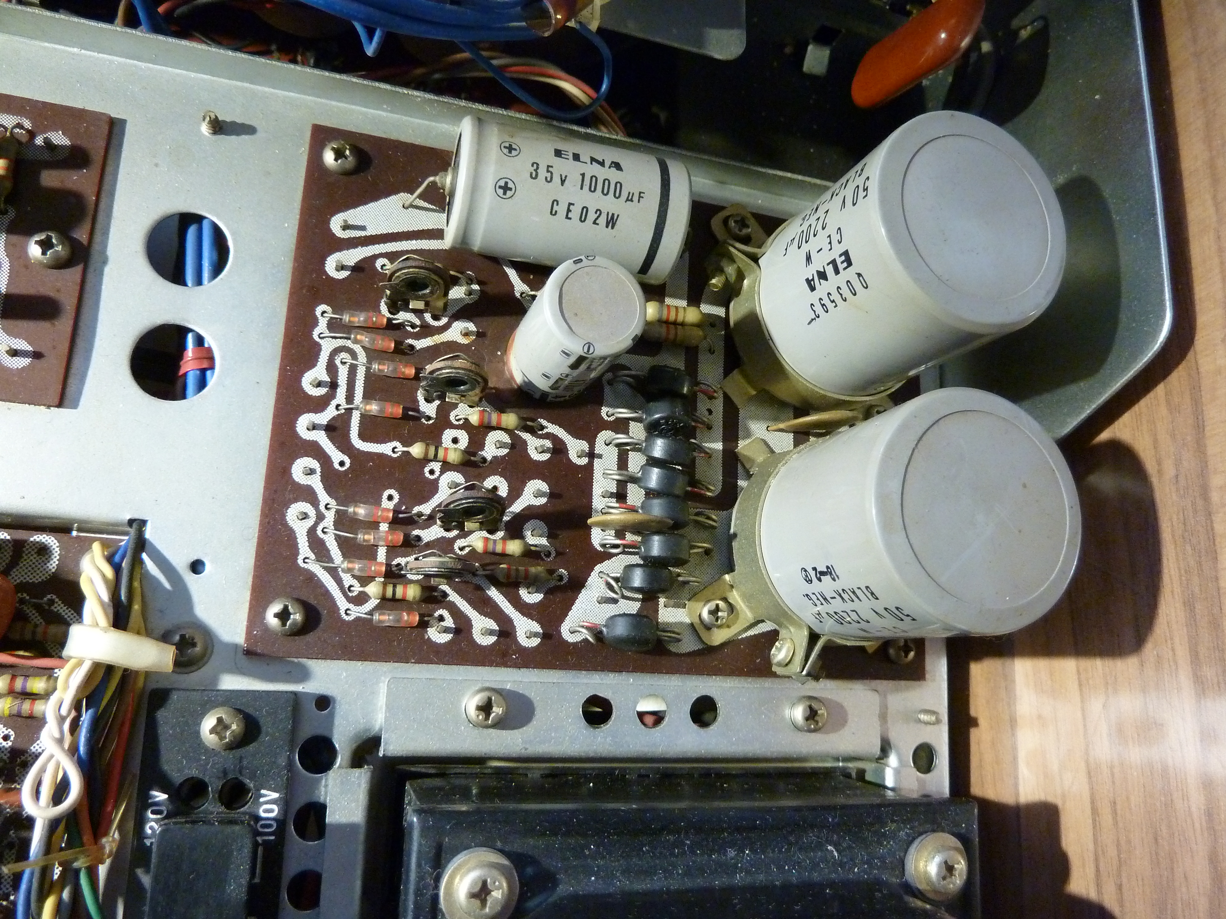
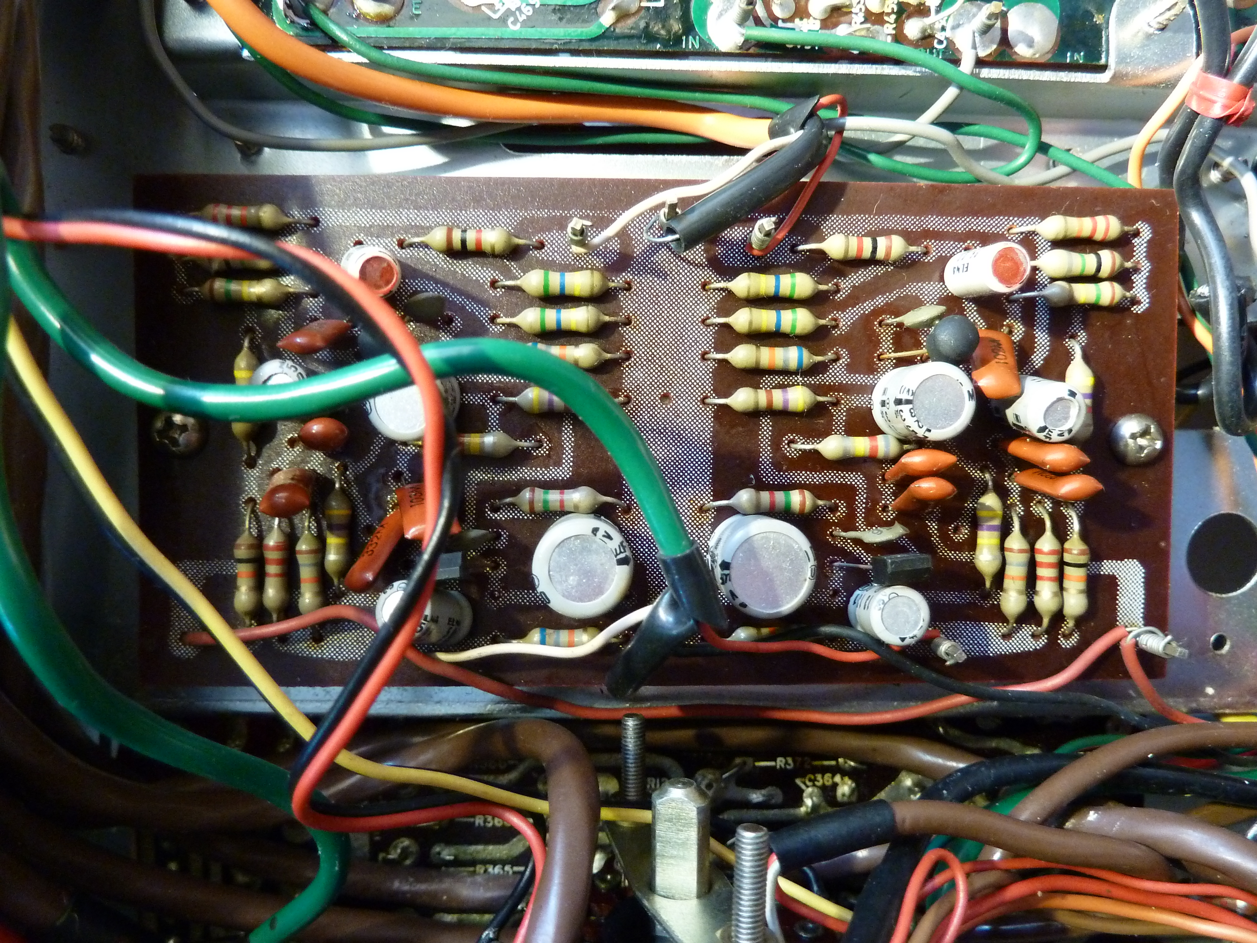
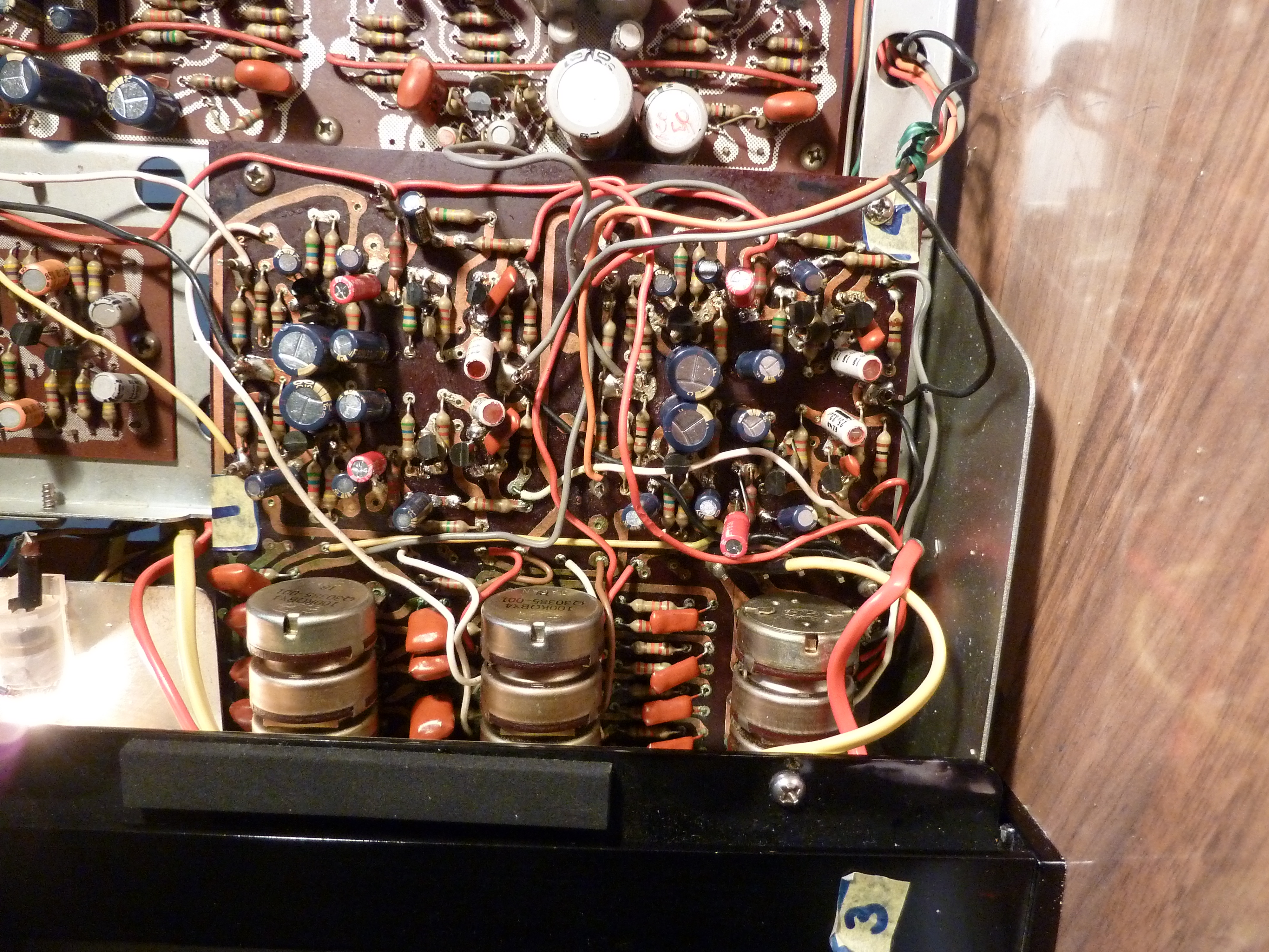
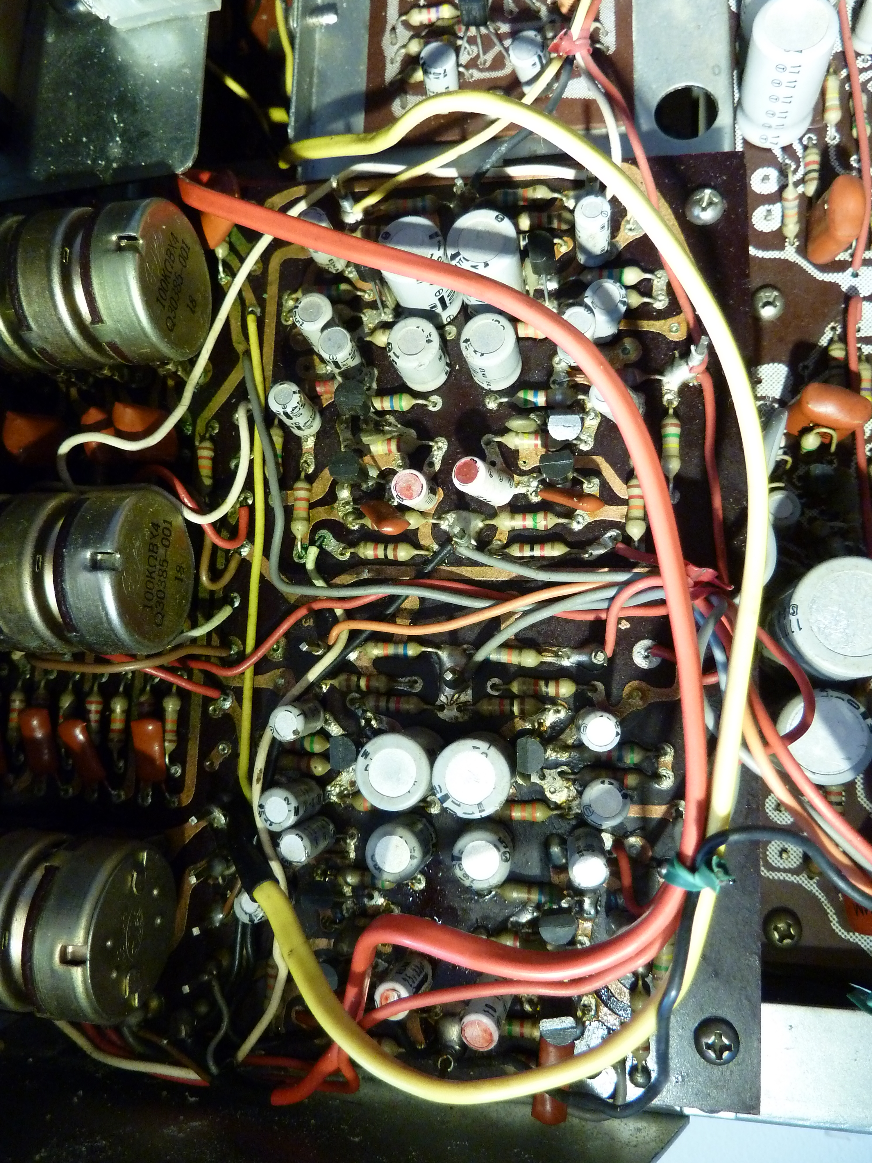
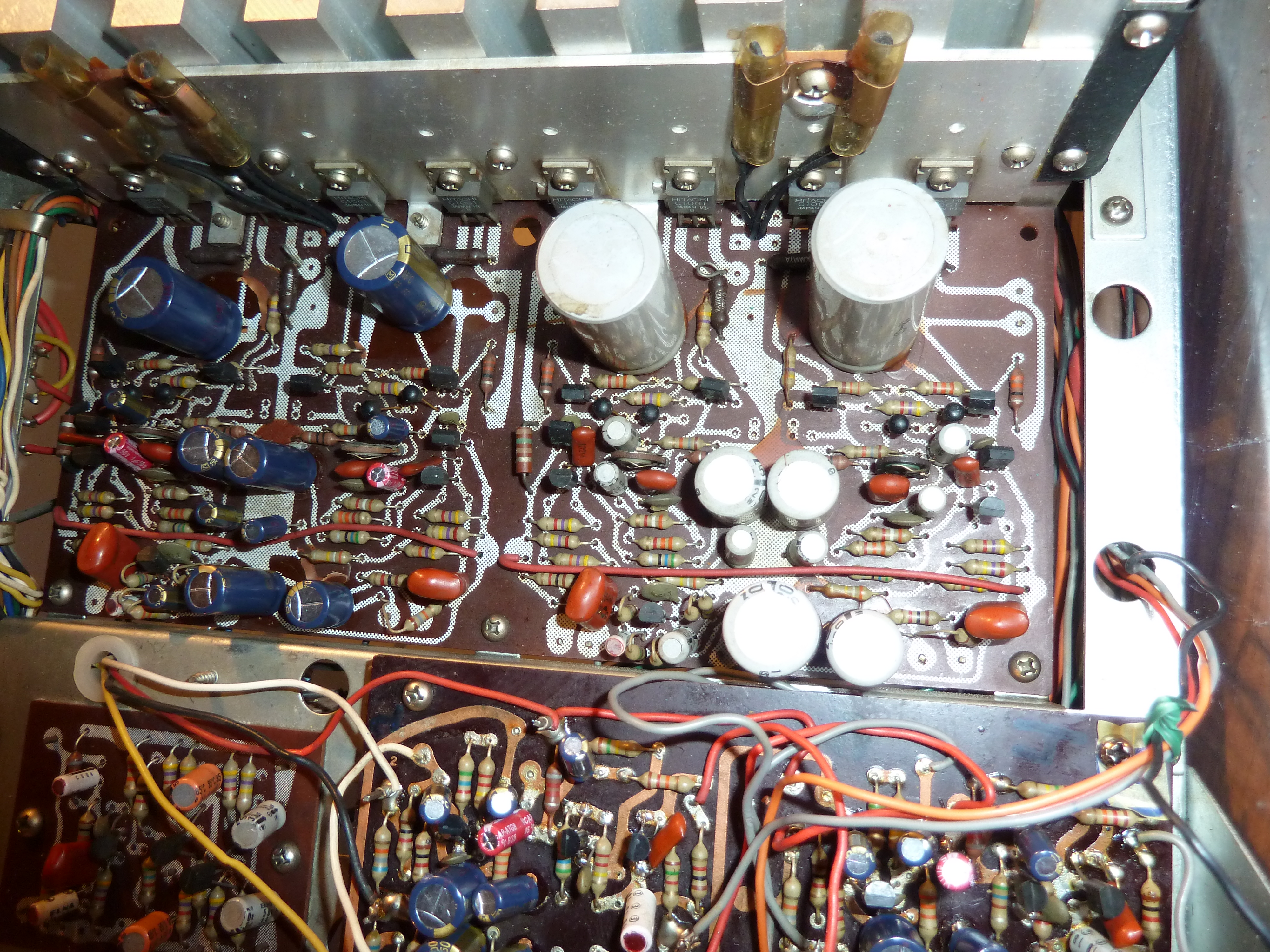
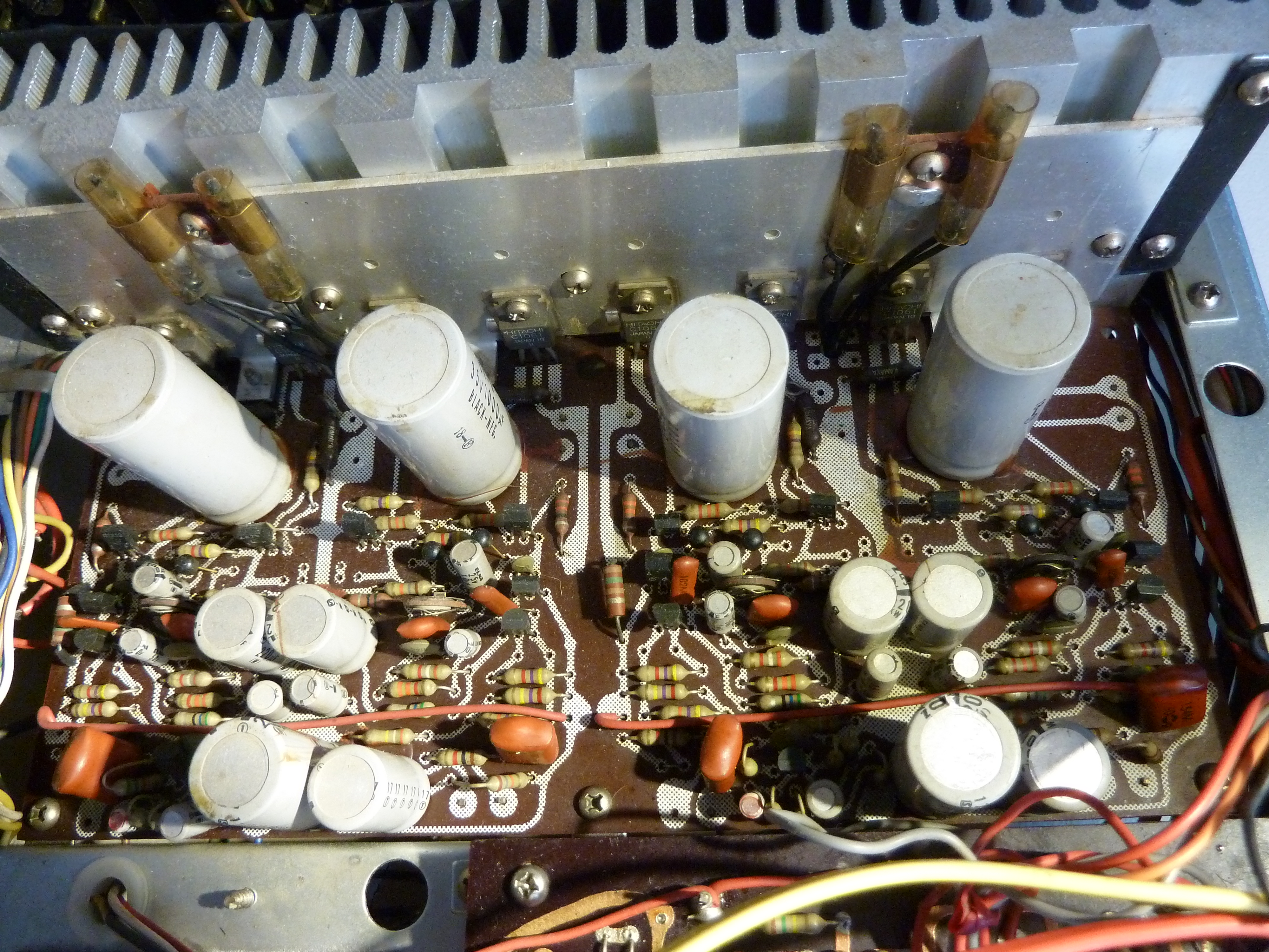
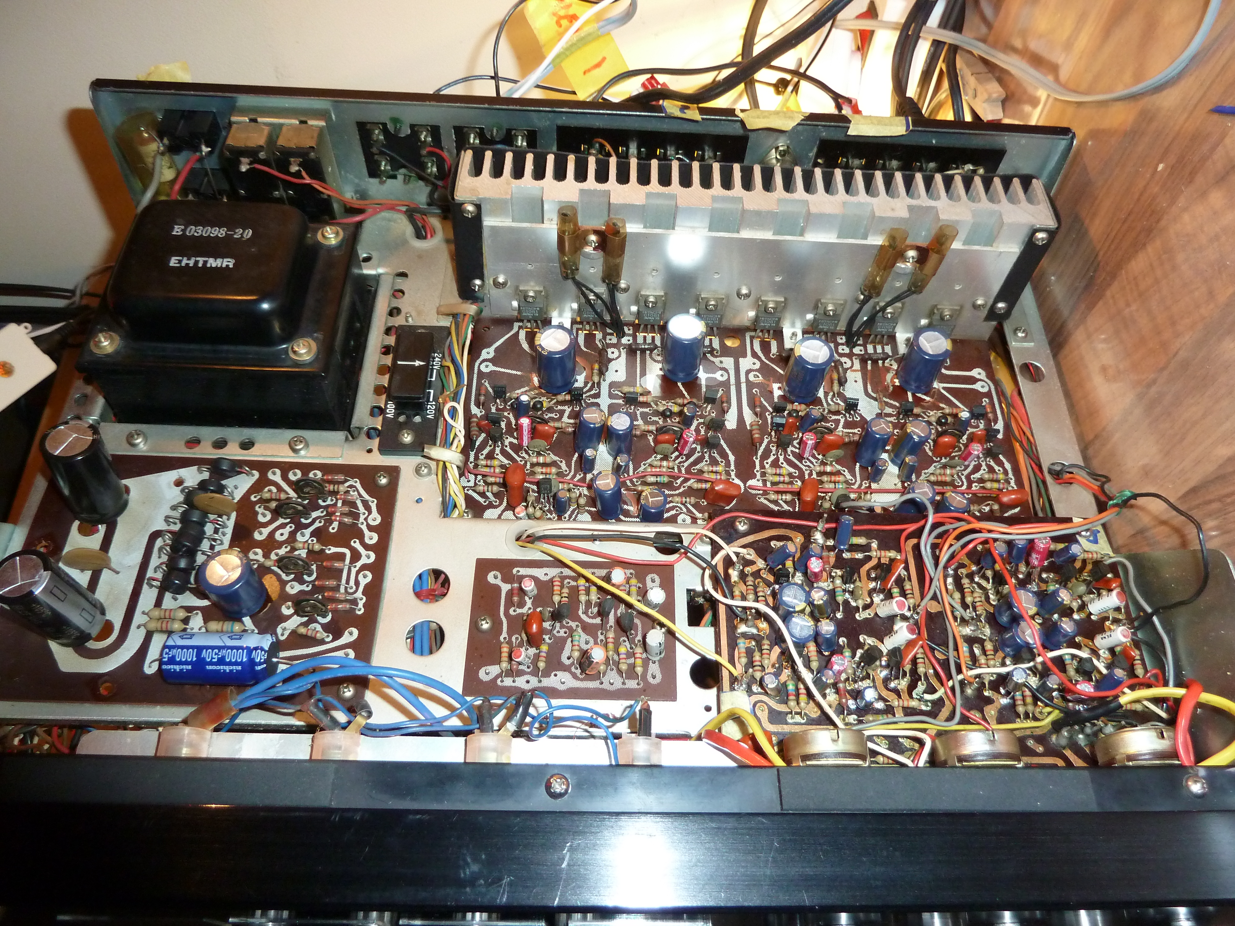
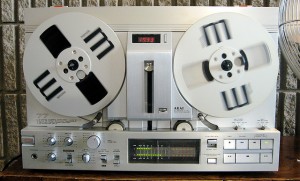
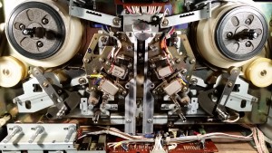
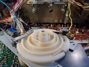
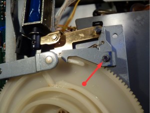
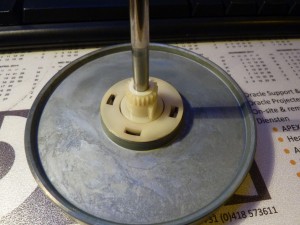
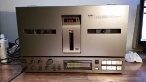
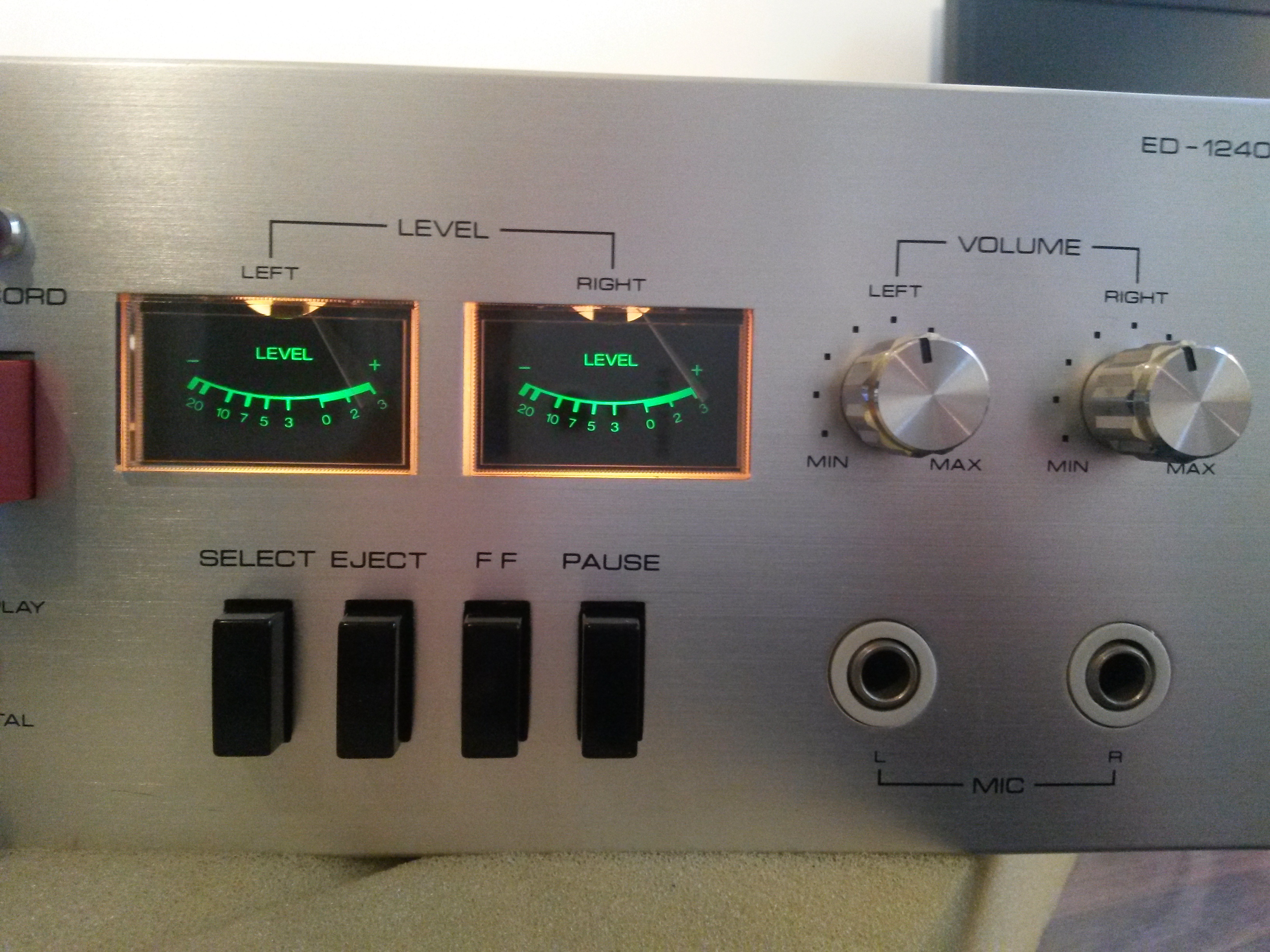
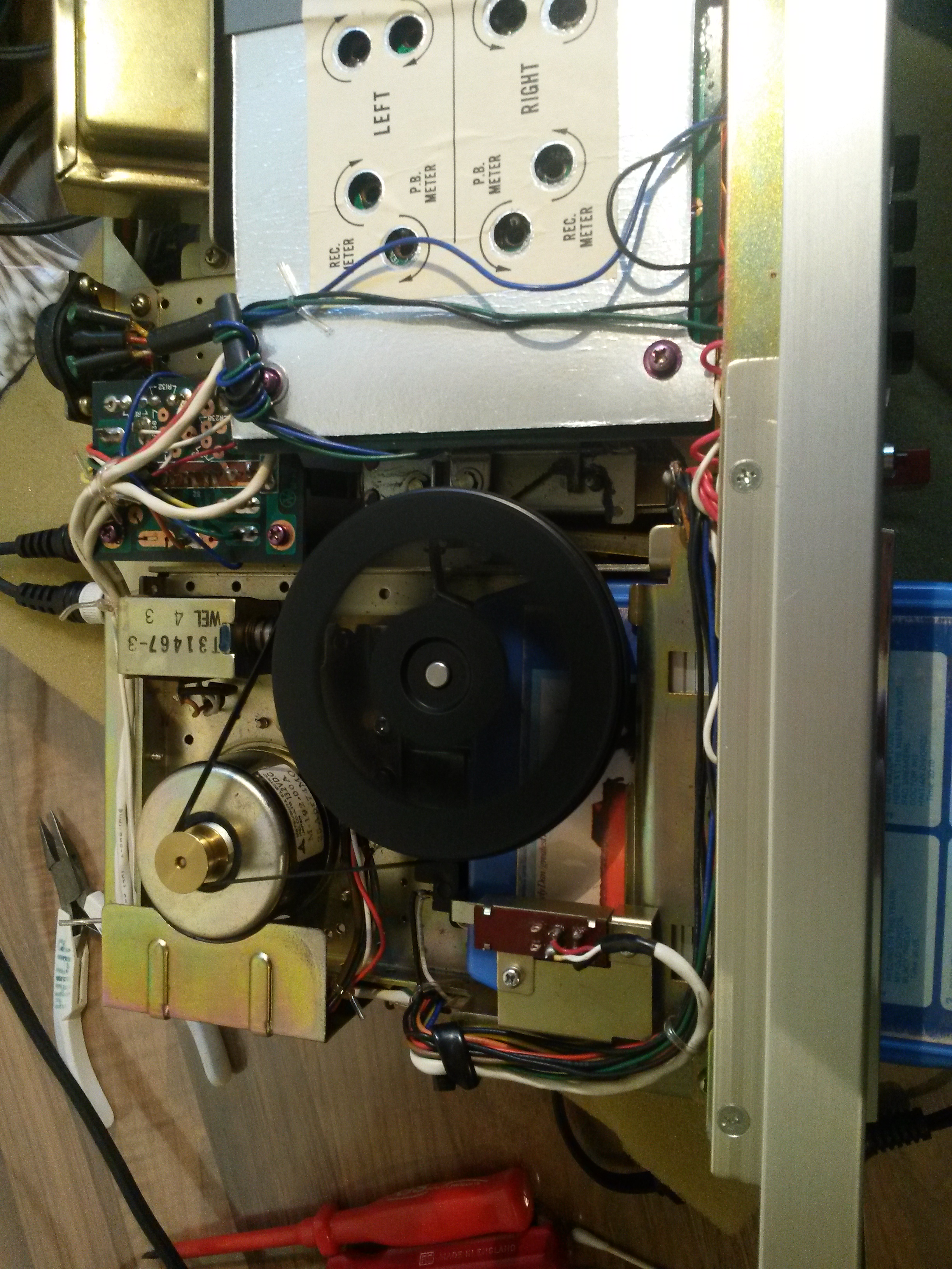
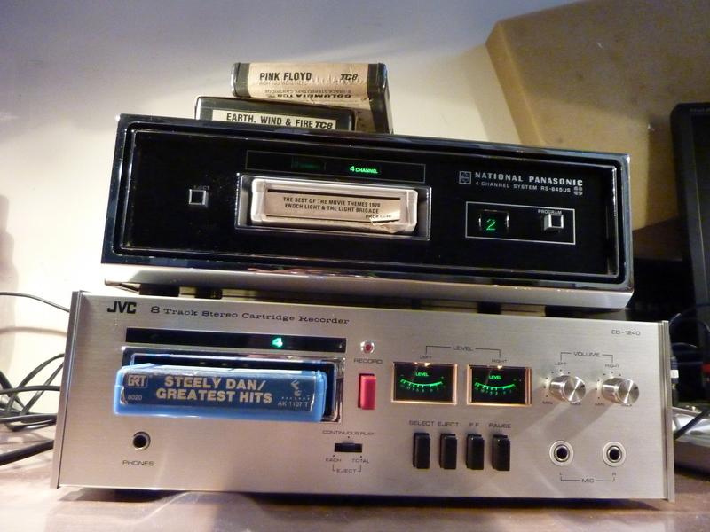 Here it can be seen on top of my JVC. At the moment the picture was taken, it was playing a quad tape as you can see by the ‘4 channel’ indicator light. In this mode there are only 2 programs, not 4 as you would find with a stereo tape.
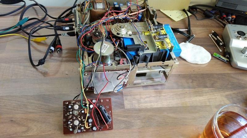
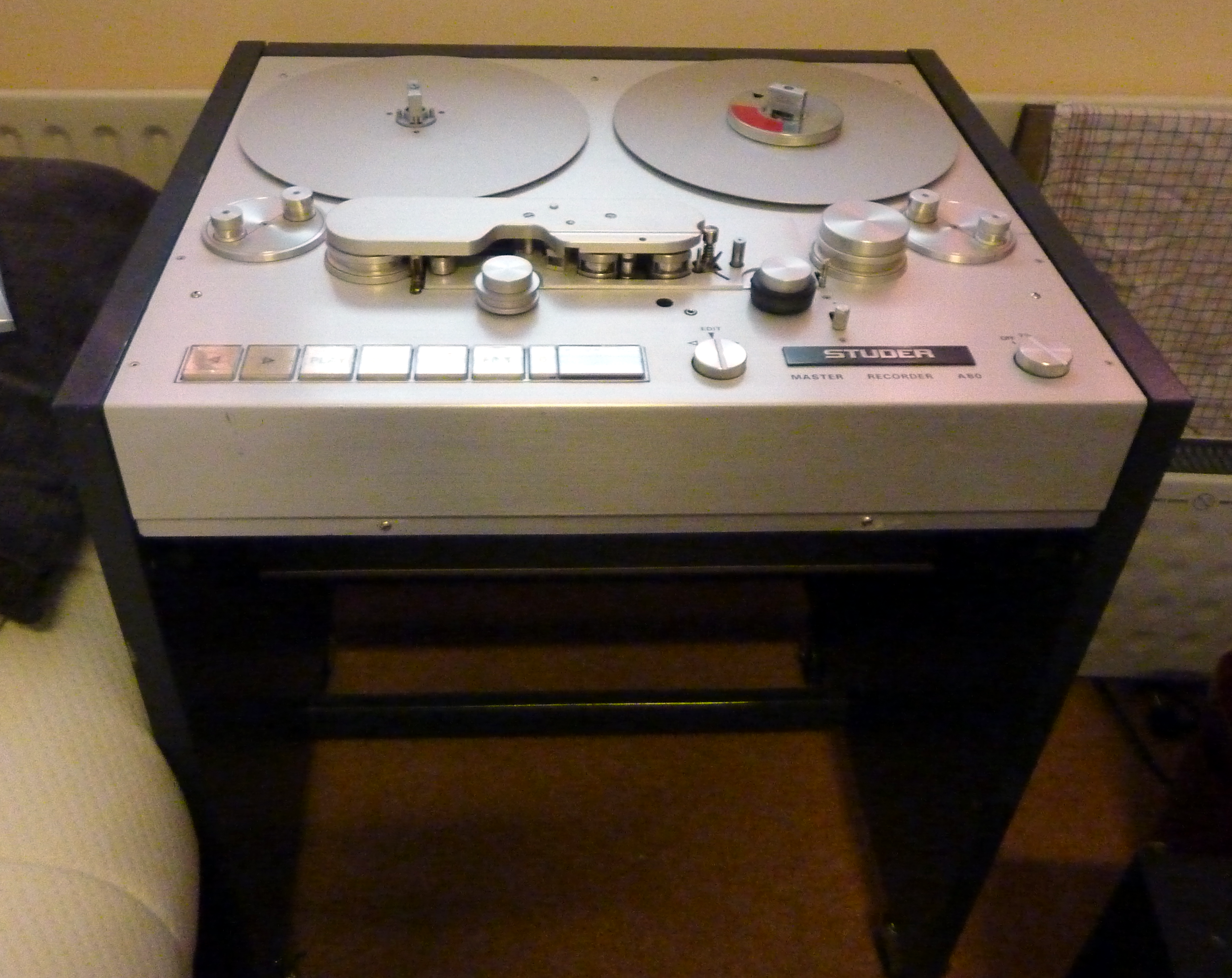
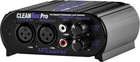
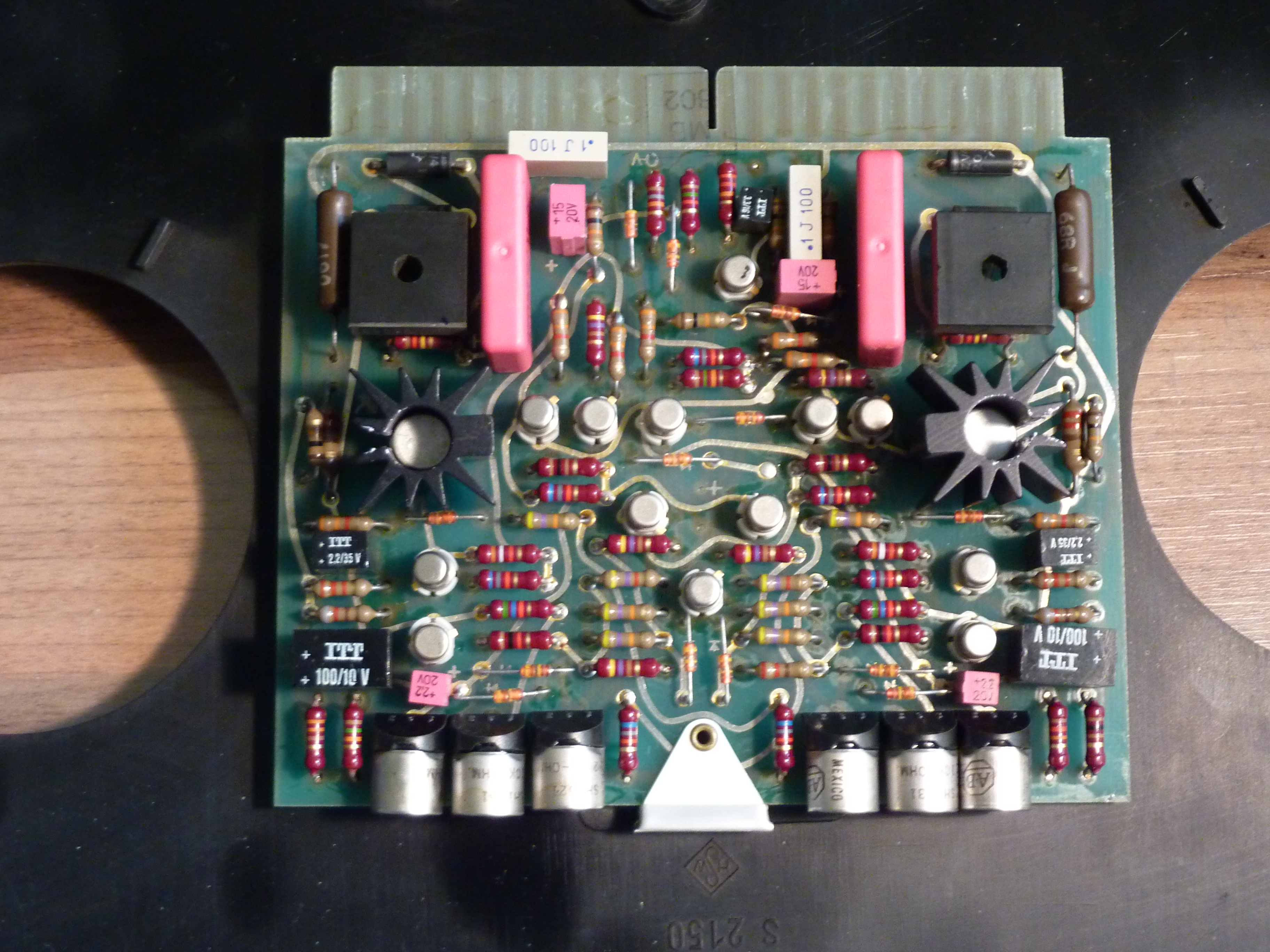
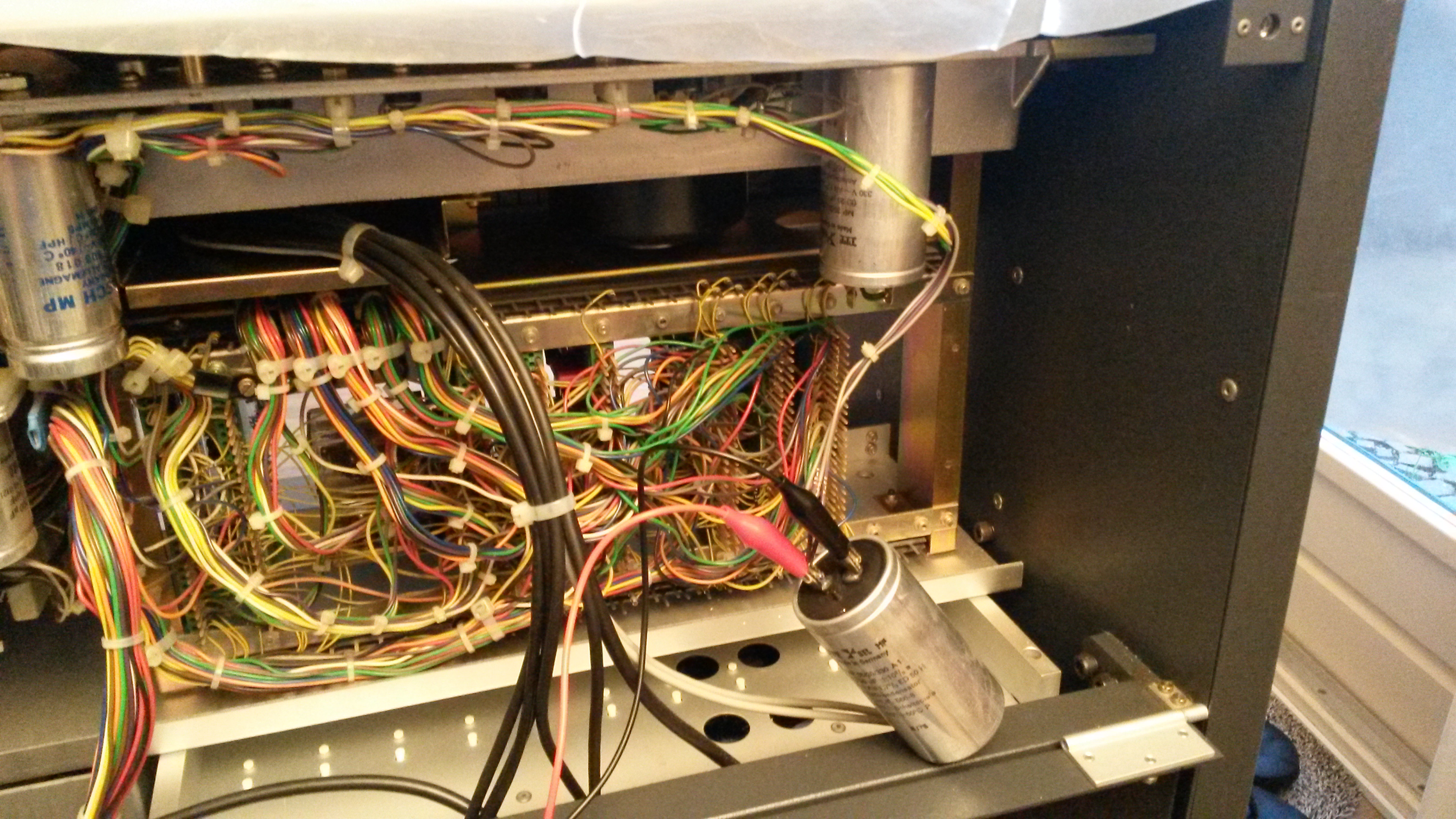
Hi, I would love to try out your 8903B py software. Your help file specifies very carefully py version and lib versions. I have a lot of SW experience, so I feel that I can beat it into submission.
I have built pete millet jonokuchi headphone amp, a 2nd with boutique transformers, sangaku headphone nutube amp, his mighty midget, 26a7 preamp. Working on his engineers EL84 amp.
Also built a tubelab TSE with 2a3 tubes.
I have an 8903B and usb interface and would love to get measurements going on all these amps.
Thanks, C
Hello Curtis,
I have created a codeberg GIT repository. I have uploaded all the files there. It works very well, but since I run a rolling distribution (openSUSE tumbleweed) The GPIB driver breaks a lot. Every time I get a new kernel, about once a week. But there is now built-in DKMS support so that the GPIB will be rebuild after each update. But check in often, it is still being ‘perfected’ so whenever there is an update, I push the new files. Also after you have ‘git cloned’ the repository, be sure to check out the README and the help files.
You can find the git repository here:
Thanks,
If you could change my display name to “Curtis H”, that would be great.
I am very interested in getting this going as well, however I am using a standard PCI type interface, which is working on Pete Millets software in windows, but I cannot seem to get your version working unfortunately. I have tried it in linux as well, but as you mentioned there are so many variables. I would like to get it working on linux preferably, windows would be acceptable because I have other test equipment hooked to the same GPIB interface on it anyway.
A brilliant open-source solution! Moving away from legacy Windows dependencies to a clean Python-based architecture is a pro-move. As an Electrical Engineering student at Telkom University Surabaya, I really appreciate your effort in making this instrumentation data accessible and extensible.
Thank you for your kind words!
-Philip
hello sir,
First of all, a very nice and neat GUI.
I tried the script under Windows 10 with a PCI NI488-2 card, but it did not work well.
So I rewrote the script a bit, the interface for Windows and I must say it works perfectly.
But one question, have you already implemented the filters?
I work with the HP8903B and I do not have HP filters but a CCITT filter, so it is very possible that there is another command for this.
I would only expect the HP filters to work if you have activated them in the script, otherwise I will continue looking.
Greetings,
Henk,
Hello Henk,
Thank you so much!
I think it’s amazing you got it working under windows.
I have not updated the app, if I would have it would have been pushed to codeberg.
-Philip
Hello Philip,
My question is whether I am doing something wrong with the controls or if the filters in the script are not yet activated?
The keys work, but nothing happens on my instrument yet; I currently have the B version and a CCITT filter instead of the HP filters.
If the filters are not yet activated, I will see if I can add this to the script.
If you would post my changes—the complete script for Windows 10—along with your script for Linux, I will send it to you so that everything remains organized together.
Regards,
Henk.
Hello Henk,
Are you talking about the high pass 400 Hz and the low pass 30/80 kHz filters?
I do believe this functionality works on my machine with the app. It has been a while. I can not verify it atm.
And yes, I would like to eventually include your script in the codeberg repo when it is working, with the proper credits of course!
-Philip